I’m architecture student in Brazil and working with earth construction using grasshopper.
My goal is to put a parameter that could control the horizontal gap between bricks in a brick wall. The intention is to make a “minimum and maximum” values of gap so that all brick lines are composed of entire bricks.
Besides this, how can i control so they don’t overlap when they reach the top of the loft structure?
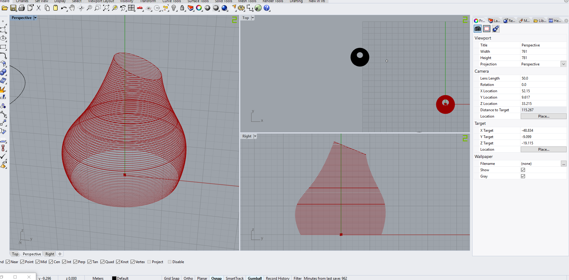
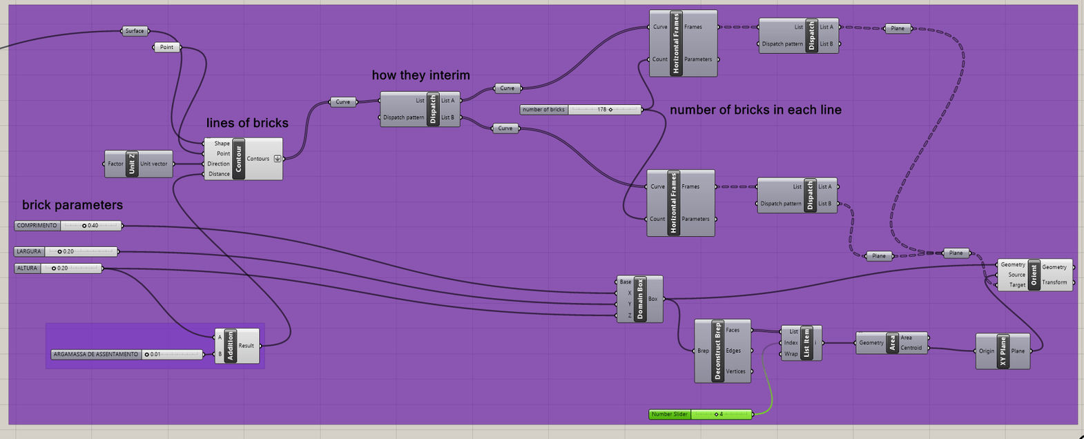
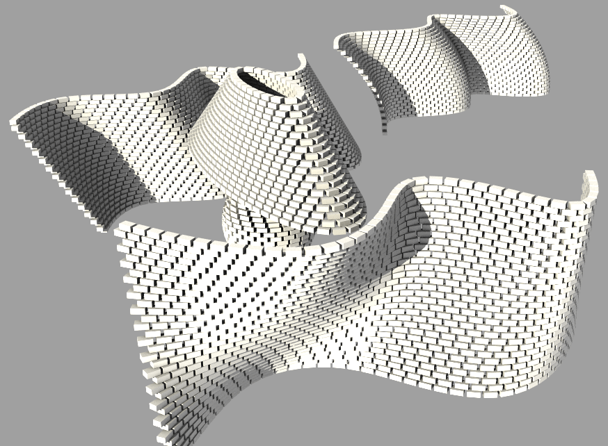
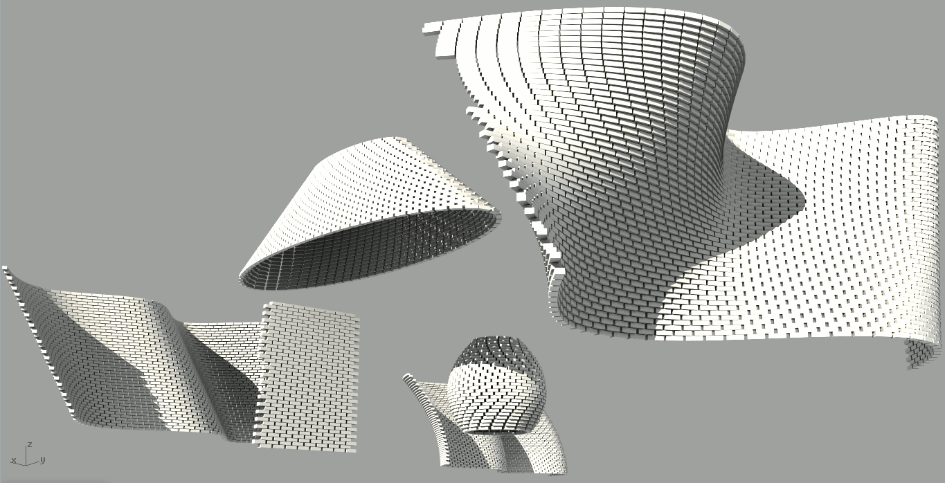
Thanks everyone for the help!! Follow the images!!
Realy nice job man!! The path worked perfectly, it solved my problem with the overlaping
bricks and i can apply even with different lofts!
Now i’m trying to put some parameter that could control that the from some high of this suface lofted, the line of bricks can have no gap, so the gaps can occur just until high from the ground.
Do you think in some way to do this? Its better if i plan the loft surface to fit in the number of bricks desired?
You didn’t post a model so I can’t speak to your particulars. I took a copy of the model referred to above and added a cyan group that offers a “Gradient” option affecting the gap. The output of the Range component can be reversed so the gap diminishes toward the top instead of the bottom.
I replaced a pair of Split Tree components with a better way to cull bricks on alternate rows.
There are some assumptions made here that I’d rather not get into changing, though I can see reasons to do so. The number of bricks per row is rounded to be an integral number, no fractional bricks at the ends, and that has consequences… such as preventing the gap from being the gradient we want due to this rounding.
P.P.S. This version (‘c’ below) adds a red group to show collisions between bricks, sorted by volume. It takes patience because SUnion is slow, but it works.
When both new gap switches are set to the old defaults (‘Gap = Even’ and ‘Div By = Rounded gap’), there are no collisions (in this model). When ‘Div By = Length’, there is a mix of collisions and holes at the seam, the beginning and end of each row.
Re-purposed and relabeled ‘H gap (min)’ slider to control minimum gap for gradient. (cyan group) Note that now top and bottom have their own settings so no need to reverseRange.
“Brick Collisions - OPTIONAL, SLOW (may be disabled)” is disabled by default. (red group)
Hey there Joseph, First of I apologize for not thanking you for the help and the attention to solve my problem. I passed the last days working in the aspect of the wall.
I tried to use the configuration you went through and as you said, choosing to have always entire bricks has consequences. So I decided to think in a new way:
I realy want the bricks to be symmetrically interspersed. So each row can have different numbers of bricks, and gaps, this gaps don’t need to be the same, but they must have a maximum spacing. With this, who controls the number of bricks per row will be the gap, but it just occurs until the height of 8 meters. From this place up, i can have no gap, the bricks continue to be symmetrically interspersed, and there will be moments that the brick is not entire brick. This is ok for me.
I thought this aspect not interspersed it’s not so good for bricks made with earth, so its a more important parameter, do you think we can return to that initial aspect, but now matching the use of this Sunion that you sugested, the dispach parameter, and the definition of maximum gap to control the number of bricks in each row?
The Model is posted below, sorry, i don’t know why they didn’t uploaded last time.
Really really thanks for your help
The .3dm file appears to be unnecessary as the GH file works fine without it?
As to the GH, I’m not sure yet what you’ve done or what you mean…? Looking at your model, I see that all bricks are overlapped with no gap at all?
One thing that might have caused some confusion - In my old models, including those versions posted above, gap was specified as a multiply factor to be applied against brick size rather than a specific distance, so it was always greater than one. This was done so that it would scale well when brick size changed. But I see in your current model that gap values less than one are used, implying actual measurement instead of multiply factor?
Not sure how much I want to get into this again so anyone else, please feel free?
Looking a little deeper, I copied the brep shape from your current model to a GH file I posted here ten days ago and immediately realized we are working at different scales (meters vs. inches?) so my brick and gap dimensions with your model yields far fewer bricks. When I scale up your brep by a factor of 20, I get ~11K bricks, similar to the ~13K bricks in your model.
If we’re going to exchange models, we need to stop changing slider values.
really don’t need the .3dm model GH works fine without it. :piscadela:
The idea was that the bricks were not overlapping and now I understood that the multiplying factor caused me confusion. However, the aspect is still that the bricks are no longer interspersed, this causes situations like this:
I believe that this way I can not build. I see that the gap gradient already happens naturally because of the shape but I would like to be able to control this GAP between the bricks as the defining amount of bricks, keeping them interspersed nonetheless.
I imagine you are busy @Joseph_Oster thank you in advance for all the collaboration, if you can not help me in this last definition, someone here would know how to help me?
Not really. I can imagine more complex solutions, like inserting a half brick every once in awhile to re-align the gaps, but they all require far more iteration and computation than I have patience for on this classic problem. If you have to cut too many bricks, what’s the point?
I apologize for the change in the slider as well as the dimensions, I didn’t bother to change them again when I sent it to you. I believe I can now align more with you, I’m still new to grasshopper but all this talk has taught me a lot and opened my mind to new possibilities.
It really would have been better if there weren’t so many bricks to break, and now it even seems like a good idea to always put half a brick to realign them. I’ll work harder here to see where I can get. I appreciate all the cooperation friend !! It opened my head and helped me a lot
Keep in mind that the old algorithm works well for more conventional wavy walls. It fails with the alignment gaps you mentioned when the number of bricks per row changes (especially on round tapered shapes) or when using the new “Gap: Gradient” feature, which mis-aligns the rows.
Also, there is no checking for brick collisions on tight turns which any brick layer, human or robot, will soon discover.
I can imagine an iterative process that builds on the previous row, requiring the bottom row to be laid out by division and all rows above to have bricks centered between bricks on the row below. Have you used Anemone?
It’s ancient history for me, and I don’t read icons… But as I recall, the multiply by two is done to generate twice as many points as you want to have bricks on each row (one point every half brick). Then a pair of Split Tree components culls alternate points using two different masks for alternate rows: ‘{0;(0,2,4…)}’ and ‘{0;(1,3,5…)}’, leaving staggered points where each row has the same number of points as the calculated ‘bricks per row’ value…
The code is remarkably simple for what it does, eh?
I’m going through this script. It is functioning as it should. I am not able to understand the multiplication calculation in the beginning. The height of the brick should be added to the vertical gaps, but you chose to multiply them both to find out the spacing between the contours. Why?
Similarly for finding the number of bricks in every course, you are multiplying the gap with the length of the brick.
As I recall, expressions of “x*2” and “x/2” are used to describe twice as many points on each row as bricks, offset by half a brick and culled later, before “bricks” are layed, IIRC. Gets tricky when the length of each row (the number of bricks per row) changes and their alignments get skewed.
This part I already understand. You did not use x/2, rather you used split tree component to select alternate courses. This is done in the right hand side part of the script.
It’s not exactly the same, but I’m working on tiles and I can’t figure out how to transition from a wall to distribute tiles of two different sizes with this pattern (1 2 2 1). Do you have any ideas on how I could achieve this? Thanks in advance!