Hi,
Please fillet the following surfaces with G2 continuity and also have a good setback at the corner.
All edges need to have G2 continuity.
I have Autodesk Shape Modeling plug-in. Please use it if it’s possible.
I’ll check the continuity using AD Shape modeling.
Thanks.
Untitled.3dm (50.9 KB)
Is that a job offer?
No,
It’s just for learning. I used Solidworks for testing that setback corner but when I brought it back to Rhino for checking the continuity at corner (using AD shape modeling), I noticed G2 continuity has not been achieved (>0.1).
I want to learn how I can do it using Rhino or AD Shape Modeling plug-in.
 you did not get my joke.
Anyways, SolidWorks and Rhino are different software conceptionally. SW is solid modeling tool, this means whatever you import in RH coming from SW will change the data. Making solid into closed polysurface.
I’m not huge expert on nurbs but I’m pretty sure SW do not use nurbs and so all surfaces will experience a stransformation that may lead to discontinuity.
If you choose to use CATIA instead of SW then you’ll have more success, but in CATIA you’ll have to use the proper workbench (app)
1 Like
hey,
you can have the fusion version free of charge 
lol12.step (68.0 KB)

well duh…
maybe you could recalculate the surfaces and rematch in vsr at least…
1 Like

Great,
Can you please explain your method?
I’ll better try to illustrate
-
filleting the edges like we usually do
-
adding flanges onto resulted edges
-
split the horizontal fillets using flanges
-
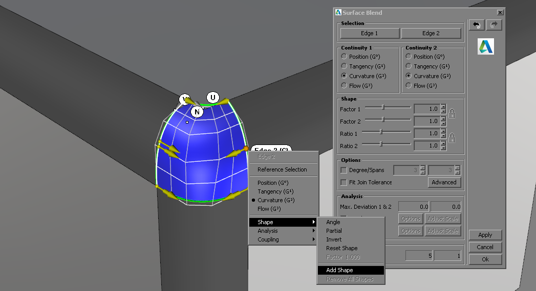
adding blend between trimmed fillets with extra shapes to get the CP mesh more uniform
-
match the blend surface to the bottom fillet with the parametrization adopted
-
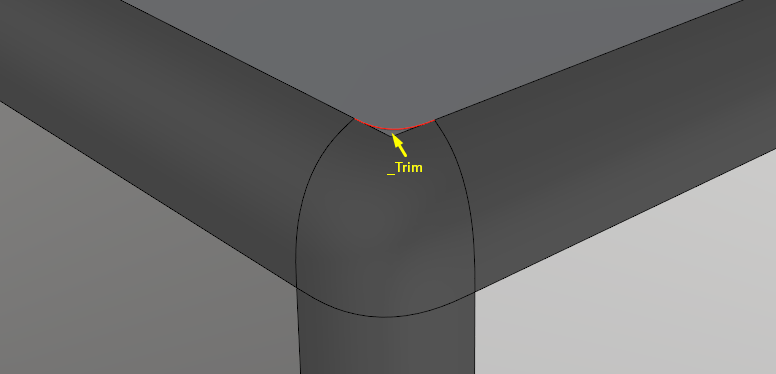
trim the top support surface using Rhino native _Trim command
-
may need some extra matching steps if necessary when G° or\and G¹ doesn’t meet the limitations


2 Likes
pirates don‘t spend money 
2 Likes
yep that‘s the right method. as an alternative for flanging normal you can use a blend curve tan to pos and split with a planar surface created from the 3 cps.This is a slower method but works better if the fillet-edges are more curved
1 Like
Very great tutorial,
I followed your steps and reached to a G2 in all the edges but when I render closely, there is some gaps visible.


How can I revise those gaps visible?
join the surface its a display issue
They are all joined. I used KeyShot to render it closely but the problem exists in KeyShot too.
1.3dm (3.6 MB)
When I zoom in on those edges there are gaps. Have you tried Show Naked edges?
1 Like
You might want to set the back faces to a different colour in a display mode. When the outside of a object is the back face colour it’s a good indicator something’s wrong.

Yes, there are gaps. I can revise them by Match Surface command (AD shape modeling) but the third edge comes out of G2 continuity. I think I need to manipulate CVs manually to reach G2 in the third edge.
Well yes you do have two gaps, here they are:

And I’m not sure if it’s possible to fix good just by matching, why because you trimmed the side fillets using curve like Tom Tom says but he also mentioned the 3pcs plane made of that curve. Your resulted trim looks like this if zoomed non-uniformly:

My guess is that you better should use a plane surface as a knife in this situation and use curve-aided knife in case of non-planar support and fillet surfaces.
Here is your gap in CP mesh:

And here’s why you can’t have G² between the corner patch and bottom fillet surface

I hope it helps
2 Likes
another rare surf user
1 Like