I don’t know if “distance space” is a correct terminology in english, it might be a german thing.
It basically regulates how tall building are allowed to be build in GER.
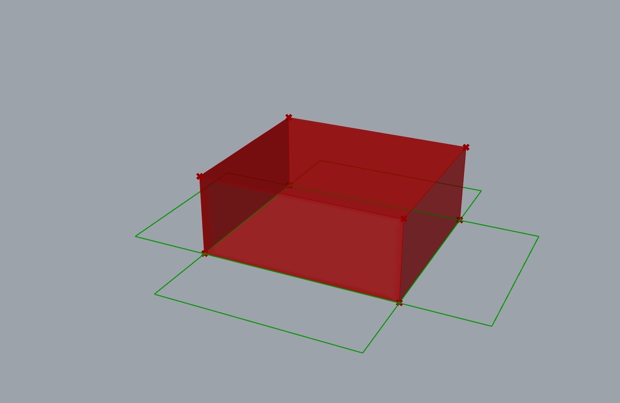
I want to automate that in Grasshopper and ArchiCAD. I have a given Brep which is changing in height. Depending on the height there should be rectangles drawn on the bottom. (basically the walls flipped to the ground on each side).
Though my solution is working I feel like there is a better one out there, mine feels a bit clumsy although it gets its job done. I really couldn’t get any more elegant solution.
This version is way better. It doesn’t care if there is a bottom (or top) on the building, and doesn’t care how the building(s) are rotated. It handles multiple buildings too.
P.S. Well, I found some failure modes… A tapered building with sloped sides requires a “round(x)” expression on the DProd(Dot Product) output, But even then, it fails to put the edge curves flat on the ground because it rotates the sides 90 degrees (from the slope angle).
Adding a peaked roof causes several additional problems.
this is just a thought -I have no idea how that specific german rule works- but I’d think to project the sides of the bounding box that contains the building, not the building itself
That’s the very first thing that occurred to me as well, before my first post. A far simpler problem since bounding boxes are consistently constructed. There is still the issue of rotated buildings though, so the BBox would have to be rotated too… Still, the more I’ve played with this, the more confused I get. I’ve seen some bizarre grafting behavior trying to handle multiple buildings, and dealing with sloped sides is no easy trick either.
@max.scheerle can you please clarify? Will bounding boxes suffice?
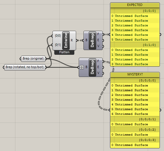
P.S. This is driving me CRAZY. It makes no difference whether the input to the second DeBrep is grafted or not, the “MYSTERY?” output remains a mystery to me?
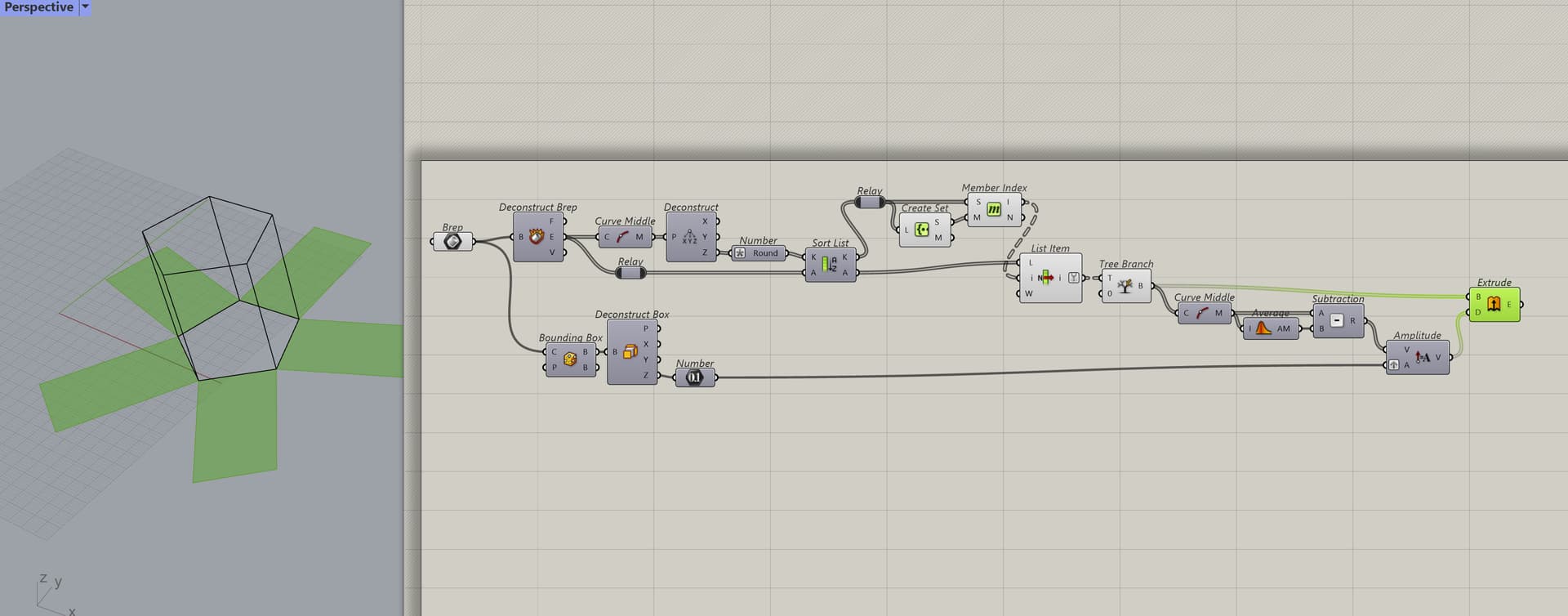
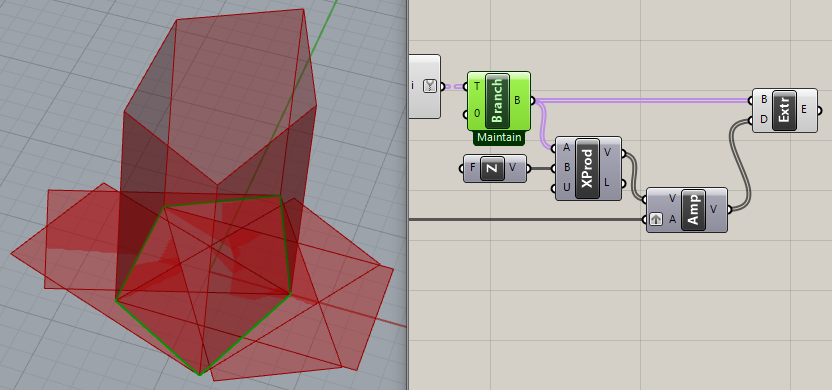
This version gives up on the complexities previously mentioned of angled sides and pitched roofs, as exemplified in five sample buildings. It rotates the sides of aligned bounding boxes around their bottom edges to be horizontal. The light purple group derives an aligned plane for each building’s BBox.
Wow first of all thank you for all those replies! I was really overwhelmed with the amount of interest in this by you guys
I need to look at all the solutions later, when I have more time.
But so far to answer your question, it is a little bit more complicated in real life of course
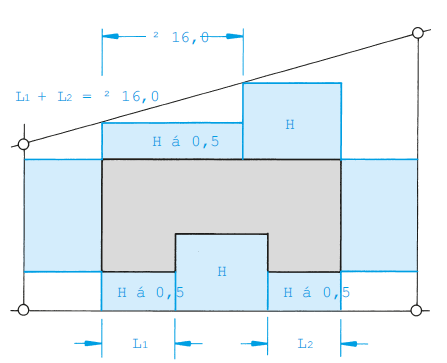
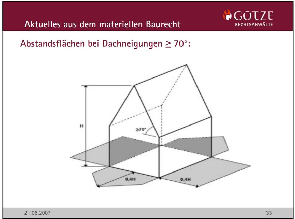
Here you can see the general idea of the rule, to regulate the volume of the building, the “distance spaces” are not allowed to overlap the borders of the site (in most cases, but there are exceptions as well)
The regulation got updated and since then you are using the real projection of the facade like shown here, literally folding down the sides of the building as they are
Anyway, thats roughly the basics of this rule. It is actually not easy to “automate” the complete process in grasshopper it seems, but as far as I’ve seen it is good for simple first drafts or with simpler structures to get a direct feedback, as you adjust the volume.
Working with the bounding box is already enough I think, sometimes maybe even better cause it gives you a buffer. Creating a first volume study often starts with cubes anyway.
In my head doing that task in grasshopper was really straight forward and easy in my head first, but turns out, it actually isnt that easy at all
You are all using nodes I never touch honestly, so I will need some time to learn what you did. But this is perfect, I want to get more knowledge about how to use lists more efficient!
That’s partly because there isn’t much activity on the forum. so there’s nothing else to do.
Your reply suggests two additional factors that weren’t considered previously:
the “distance spaces” are not allowed to overlap the borders of the site
This gives a context and rationale for the rule that was previously missing, though I’m not sure it affects GH algorithms unless property boundaries are provided. However, it does explain why bounding boxes are not adequate for the task.
The diagrams showing how roof pitch affects height considerations also argues against bounding boxes and complicates the problem considerably.
Of the many complexities that I encountered yesterday (rotating surfaces OUT instead of IN, buildings that are not square to ‘World XY’, missing bottoms, sloped walls, pitched roofs), the most significant are “walls” that consist of multiple faces.
Examples:
The triangles below pitched roofs drawn separately from the wall below.
Each wall of floors in a multi-level building drawn separately, even though they are co-planar.
Sides of a building that are fragmented as in his image you posted:
Agreed, it’s not easy at all.
P.S. A slight simplification to finding an aligned plane for each building’s BBox. (purple group)
Yes, but only if the base polyline of the extrusion is constructed as expected. In this case, the list of division points needs to be reversed to be correct (or the polyline curve must be flipped).
P.S. Or you could Flip the curve segments from Branch, but how do you know? This is one of the complexities I was dealing with yesterday. (rotating surfaces OUT instead of IN)
Probably the safest would be to offset the polygon and then make a vector from each midpoint of the segment of the midpoint of the offsetted. But it is definelty not a nice solution.
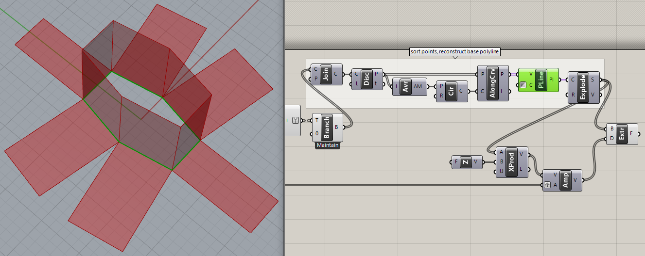
My solution was to sort points and reconstruct the base polyline. It doesn’t matter whether the initial list of points is reversed or not. This also works when rotating the walls instead of extruding the base segments. It does get complicated, eh?
I know you dont like to use scripted components, I am sure you can do it by comparing vectors.
Just wanted to mention I found there is a Curve.ClosedCurveOrientation Method in Rhino common, which could be used like this:
private void RunScript(Curve crv, ref object A)
  {

    A = crv.ClosedCurveOrientation(Plane.WorldXY) == CurveOrientation.Clockwise ? true : false;

  }
Just for kicks, I started playing with a shape similar to the diagram posted yesterday:
And found that sorting points along a circle failed miserably in reconstructing the base curve, even when it was already oriented correctly. So I looked at your C# ‘ClosedCurveOrientation()’ component and thought it would be better if it returned the curve I want instead of a Boolean result that requires more handling, basically a conditional Flip Curve.
I tried it in Python and hit a snag I couldn’t solve, so started a new thread just for that: