Here’s the ReadMe about the thread generator, that gives a little explanation.
Intro: ChiralSym’s Thread Generator (4.5.4)
I wanted a thread-generator for 3d-printing custom threads, and this is what I came up with. It allows you to input a custom thread-profile and the number of thread-starts. It then generates internal and external thread surfaces based on a thread-tolerance.
Brief Description:
The geometry is generated by lofts, with the cross-sections being in planes that contain the thread-axis. You can think of this as sweeping out a surface while translating (along) and rotating (around) the thread axis.
This is “approximately” what happens on a machinist’s lathe during single-point thread-cutting.
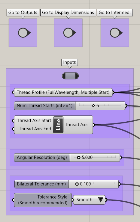
Inputs:
(1) Two points representing the start and end of the thread-axis.
(2) A curve that represents a full-cycle of thread tooth profile.
(3) Number of thread-starts.
(4) An angular resolution. This is the sampling-resolution used to generate the thread-helix.
(5) A thread tolerance. The external-threads (bolt) will be smaller by the thread-tolerance. The internal-threads (nut) will be larger by the thread-tolerance. That means there will be twice the thread tolerance between the internal and external threads.
IMPORTANT NOTE: The position and orientation of input curve (2), is very important in THREE ways (not obvious):
(A) The position and orientation of the curve(2) affects the output geometry.
The START-POINT of the curve sets the pitch-radius of the threads.
The END-POINT of the curve controls if the threads will be tapered or straight.
This means the position, orientation, and geometry of the thread-profile (2) controls the thread-pitch, pitch-radius, and taper of the final thread. See (B) and (C) for more details.
(B) If the thread-axis and the thread-profile are co-planer, then we generate the thread as follows:
First, we make multiple copies of the thread form, and Join them together, end-to-end, into a big curve.
This big curve sweeps out a surface as it is translated (along) and rotated (around) the thread axis.
Therefore, the thread-profile (and its relationship to the thread axis) generates BOTH the thread pitch, and the thread-taper.
(C) If the thread-axis and the thread-profile are not in the same plane, then we first do a “minimal” rotation to get the thread-profile (2) into a plane that contains the thread-axis (1). If needed, you can output (Grasshopper bake) the final oriented thread profile, as well as various specifications, such as the thread-taper in degrees, and the thread-pitch.
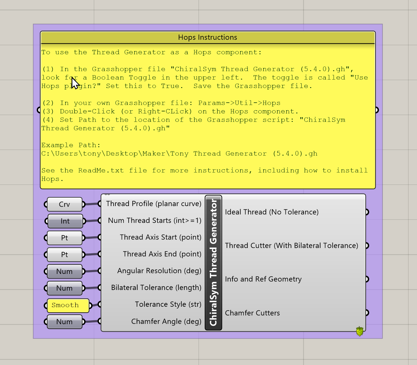
Outputs:
(1) A “thread-cutter.” This is a “thin” helix-like solid (closed polysurface). The thickness of the thread-cutter is twice the thread tolerance. Take a cylinder, and Boolean-subtract away the thread-cutter, and you’ve cut matching internal and external threads.
(2) External threads (bolt) without tolerance. I call this the “idealized thread.”
(3) The thread-profile, but aligned and positioned for Loft(s) along the thread helix.
(4) Miscellaneous additional info about the thread specifications, such as thread pitch, pitch radius, axis length, taper, etc.
The simple examples in the .3dm file take a few seconds to compute. Super-complicated threads, with a huge number of thread-starts, can take much longer (minutes).
In Demo.png, you can see a “fractal like” thread. That took several minutes to compute, and is pretty much the limit of how complicated the geometry can be. Any more complicated, and Rhino’s geometry engine starts breaking down. I don’t know how to make it any faster.
Help:
If more detailed instructions would be helpful, then just let me know.
If you find any bugs, or if you have suggestions, please point them out.
I’m only working on this project informally (for my own use), so I may not fix all bugs, or implement all suggestions, depending.
If you find this useful, then give a thanks! My goal is to learn Grasshopper and build tools that are useful for others.
Technical Notes
Some mistakes I made along the way:
(1) I used Sweep2 at first. Sweep2 is good for threads with no taper (straight), but cannot be used to generate tapered threads! So I ended up using Loft.
(2) At first, I used Offset Surface to generate the thread tolerances. But Offset Surface is computationally expensive, and very complicated. Sometimes it would fail in unexpected ways. So instead, I use Offset Curves, and then use the offset curves to generate the surfaces with tolerance. This is faster, and more robust (in my experience).
(3) The final solids are stitched together with a Brep Join of the helical surfaces and planar caps. However, Brep Join fails if a surface either self-intersects, or touches itself. This means the helical surface can’t be a single surface (ie: not a polysurface) and used to make a solid, because it has edges that touch its own edges (self-touching). We can fix this by splitting the surface into two parts, and join them into a polysurface. Then, each surface of the poly-surface does not self-touch, and Brep Join will work.
License:
This project is released under an Open MIT License.
See LICENSE.TXT.
Sincerely,
–Anthony K. Yan (“ChiralSym”)
(2023-02-12)