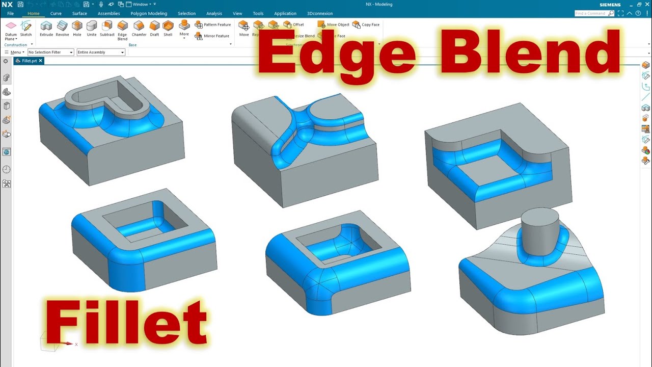
I wanted to rhino but on web ther are many peoples that say it’s really bad at filleting and some other say that it’s good and you have to know how to ready model for it and there is couple commands for it
Which opinion is correct about new versions ?
Also how rhino fillets stack up against other softwares ( catia , Siemens NX , alias , solid works , plasticity , … ) ?
In my opinion, all you said is true. There is no contradiction with this.
Rhino is a direct modeling software. Its automated fillets are becoming much better, but in comparison to parametric CAD, like Catia, Fusion360 or Solidworks, its significant weaker.
If you are used to „it-works-in-almost-always“, then Rhino can be frustrating
But if you know how it works, you can model all sort of fillets manually. If you know what you are doing, you can achieve better results than any algorithm will do. I had cases, where a fillet in Catia failed and I modeled them manually in ICEM or Rhino
Alias and ICEM Surf as direct model software offer slightly better Surface tooling, so in my experience its easier and faster to model fillets manually with them. But this is something you only need, if surface quality is key. Some years ago I did car exterior design, and we modeled all fillets manually. I would not do this in Rhino, still you can.
Rhino is a Swiss knife, has all tools, but it can feel frustrating. If you see fillets as a the hardest part of surface modeling, you definitely see the limitations. But again, if you know much about surface modeling, you can use Rhino for almost anything. I would depend the choice on your actual goals. Because producing proper fillets is a post-process and should be done perfectly only once per part.
If you plan to change your shape a lot of times, then a parametric CAD might be the better choice overall, even if its more expensive.
The 1st video shows a very wrong technique that only looks “good” at first glance, but in reality it’s a bad habit that teaches the other modelers to find shortcuts that lead to bad surface quality and further possibility to errors. Those two patches with random shape are not as smooth as what the viewport suggests. If you aim to make a product design for manufacturing, you don’t want to use that flawed technique.
This could be made far better in Rhino with a manual blend surface between the small and the large radii.
That is the methodology you are forced to use by solid modeling programs.
With this approach, first you have to boolean all the features together into a solid and then you have to pick edges to Fillet. That works in simple cases, but make it complicated with lots of overlapping fillets and it doesn’t work very well.
IMO this is not a good approach to making Fillets in Rhino. Its pretty much guaranteed to fail except in exceptionally simple cases.
A much better approach is to think of fillets as connections between features.. For me Fillets are not a post process. Filleting is included at almost every step of the process.
Here is an example I posted a few years back: doodle.3dm (3.3 MB)
In this example, the first fillet connection is the ellipsoid feature to the central body with a 30mm fillet. Then connect that to the base feature with a 15mm Fillet loop. Then connect that to the two cyan bosses with a 15mm Fillet loop. Then connect that result to the two grey side pieces.
In this example, making the fillets takes less time than making the base features, and more features could be added in and connected with more Fillets.
In the end you have a solid that has 175 surfaces. Around 150 of them are fillets.
That’s crazy!
Thanks for sharing the file, I looked into and yes is a very interesting tutorial for fillet methodology.
Did you used FilletSrf or FilletEdge (if there’s any difference)?
There is no an universal rule. It all depends on the intended design. In this example, adding the fillets took considerably more time than creating the primary surfaces, because many of the fillets act as secondary surfaces, as well. They are not just final rounded edges. Instead, they are used as a base to build other features at a later stage.
As discussed in another thread a few months ago, the aforementioned script is extremely useful, but it still failed in several cases during the modeling process. Rhino’s fillet tools also failed, so I had to use a combination of 4-5 different methods to achieve the desired shape.
It depends on what you do. Of course it makes sense to model with fillets in mind. But if you model a shape and apply all fillets perfectly in all stages, then you waste so much time. I mean how often did I model fillets just because management wanted best visual quality for presentation. Then they decided that everything needs to shift 5 mm left. And suddenly the surface layout was obsolete. With a clear theory you can fillet almost everything and with some experience on how the main surface need to play together and how they should “accelerate”, you can create good conditions without the need to model the fillets. There are exceptions, but doing fillets in each iteration in a direct modelling software is a gigantic waste of time.
it means that what you are suggesting cannot possibly work in Rhino.
Unless they want it to always fail the user should not use the strategy you suggest for making fillets in Rhino. it can only work in exceptionally simple cases.
The problem is that people don’t create conditions to properly fillet surfaces. The lack of knowledge and limited tooling in Rhino is the problem for this approach. I have created several production-ready car exteriors and I do have some experience. Its maybe true that its particular hard in Rhino, since I did it predominantly in Icem Surf. And I’m not denying that there are situations where it matters to consider the fillet in the entire modelling process. But in the majority of cases it shouldn’t matter.
In Rhino it usually fails because of easily creating miserable surface quality. One reason of “class A” modelling, is that its much easier to fillet (and to do other follow-up modelling).
But sure, If you provide multi-span, weighted base geometry, its significant harder to continue on stronger curved areas, as fillets usually are. A fillet is more or less a non-forgiving magnifier for poor modelling.
@menno If you need the source code or anything else, feel free to message me privately and I’ll send you what I’m currently working on. Right now I’m trying to fix a few selection-related bugs, but in the meantime you can take a look at the interface and see how it’s coming along.
That’s fine, but its all useless information to a poster asking about making fillets in Rhino. The OP is not going to get a job modeling production-ready car exteriors using Rhino. Its extremely unlikely to happen.
But there are millions of automobile components that require no knowledge of “class A modeling”, but most do require competence in making rolling ball G1 Fillets. For every job in the OEM or after-market automobile component workspace that require a CAD jockey with knowledge of class A modeling there are 100 jobs that don’t, but those jobs do require competence in making rolling ball fillets. If you look at a brake caliper or alternator bracket or other drive train or mechanical components on a car they often have the majority of surfaces as fillets. The surfaces that are not fillets are usually just simple planes, cylinders, cones spheres etc.
The pictures Bobi posted above are a good example. Nothing at all complicated with the base surfaces, mostly planar, but there are hundreds of fillets connecting them. The point I was making is that if you take the approach of boolean all the base surfaces together to make a solid with lots of sharp edges and then try to go around rounding all those sharp edges with fillets, in Rhino that is going to be a nightmare. IMO that’s a bad strategy in Rhino. Whether it works or not in another CAD program is irrelevant. This topics subject is not about some other CAD program.
The part whose pictures I uploaded as an example took a good amount of time, because most primary surfaces are curved. All vertical surfaces are slightly curved due to the shape following the rear panel gap between the rear fender and rear engine cover of the latest Porsche 911. This is an aftermarket bracket for holding a custom rear wing whose columns are also slightly curved due to the exterior design.
There are fewer flat surfaces, mainly at the bottom and where you see the reinforcements.
Two horizontal large fillets with variable radius meet together in the middle and form a horizontal Y-shaped fillet joint. These are primary surfaces made earlier in the design process. They are both curved, which made the subsequent filleting with the rest flat surfaces more complicated than usual, because Rhino failed to create fillets in some areas.
Another reason for the failures was the requirement to use the same radius in multiple steps of the filleting. It’s easy to add extra fillets whose radius is gradually smaller, but you know that combining same radius fillets that meet together produce errors sometimes due to the ball corners where the fillet pairs meet.
Also, some areas required 3-sided end fillets that failed due to Rhino’s inability to build a proper tip of the common control point. In most cases it built a slightly shorter 4-sided surface, so I had to modify the tip via the “Set point” tool to combine all end control points into a single one and snap it to the desired location.
I design a lot of automotive components, both original ones with my design and reverse engineering from 3d scan data of existing components. Nearly all 3d scanned components include some unusual area made from a random shape that’s not a straight cylinder. These areas easily make the filleting complicated.
Even “hidden” components such like an A/C box have a swirl shape of the main body due to the need to accelerate the air stream inside. Nearly all “cylinders” are actually truncated cones with at least 2 degrees of draft angle, because they need to be expanded from the injection moulds.
The same goes for the “flat” surfaces. Most of them are inclined to allow an easier release after the injection moulding. Some of the “flat” surfaces are curved, too.
Most OEM components include super ugly automatic fillets typical for Solidworks and other CAD programs that use the Parasolid kernel.
As seen from other threads (like the one where we discussed the importance of G2 blends), ugly automatic G1 fillets are also used in plenty of products such like home appliances and consumer electronics. This is a very bad habit that makes no sense, because the lack of proper smooth G2 blends destroy the overall look of those products.
This is something that should be pointed out in the training material. To obtain easily manipulated single span surfaces, one can even accept a considerable gap between surfaces, as in the case below. FilletSrf doesn’t know anything about “edges”, and so, the “terrible edge gap” that EdgeContinuity shows to the user disappears in the filleting anyway. Classic industrial design education provides a clue - a fillet is a transitional surface between surfaces, and has nothing to do with “edges”.
In other words, no, Rhino’s fillets are actually very good.
If you want it to just work-Rhino’s filleting tools are fairly terrible at anything beyond basic shapes. If you want to spend more time than the original modelling took manually doing fillets using multiple techniques, then it works fabulously.
Obviously there are some very skilled people on here who live and breathe it who get great results but I don’t think they work very well.