Hi there
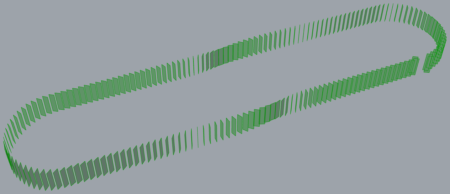
Whenever I do definitions in GH, I always have trouble understanding how to align planes. I have this initial curve with 184 planes, that I would like to be aligned to the main curve. The loft comes from two curves, with one offset of 10 cm, so the surface is not straight.
My logic was to create a vector between the center and each surface, but when aligning and trying to obtain the tangent, I always find myself in big trouble solving this.
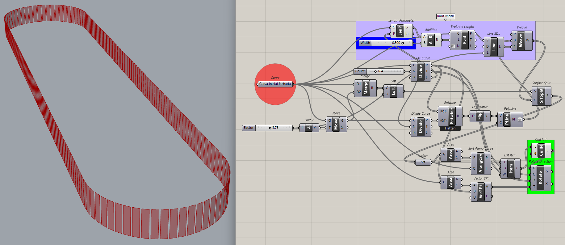
I would deeply appreciate some input and some advice or tips for future works like this! thank you 116_Fassade.gh (18.7 KB)
Maybe you mean this? Also i do not know what you’re trying to do with scale, but be sure that two lists shown with orange arrows are corresponging, you might need to sort the list after Surface Split component.
Hi! Thank you for your reply Fassade is in german (:
I see the problem! but why before it was working ok? I never saw the divide surface getting error. The loft between the two curves is not in the same plane so I understand it could turn into a beep, but the division I intend to do in the surface must be parallel between each other (I tried doing this by dividing by length both curves and creating a line between two points but they were not straight lines)
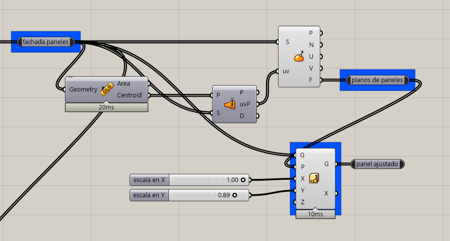
Thats the part that I do not understand how to solve properly, since every surface I created from the split must be aligned with the centroid of the original curve (or just aligned with the loft that I created at the beginning). The scale UV is because I need to leave a gap in between each panel but maybe I can achieve this in another way, im not sure
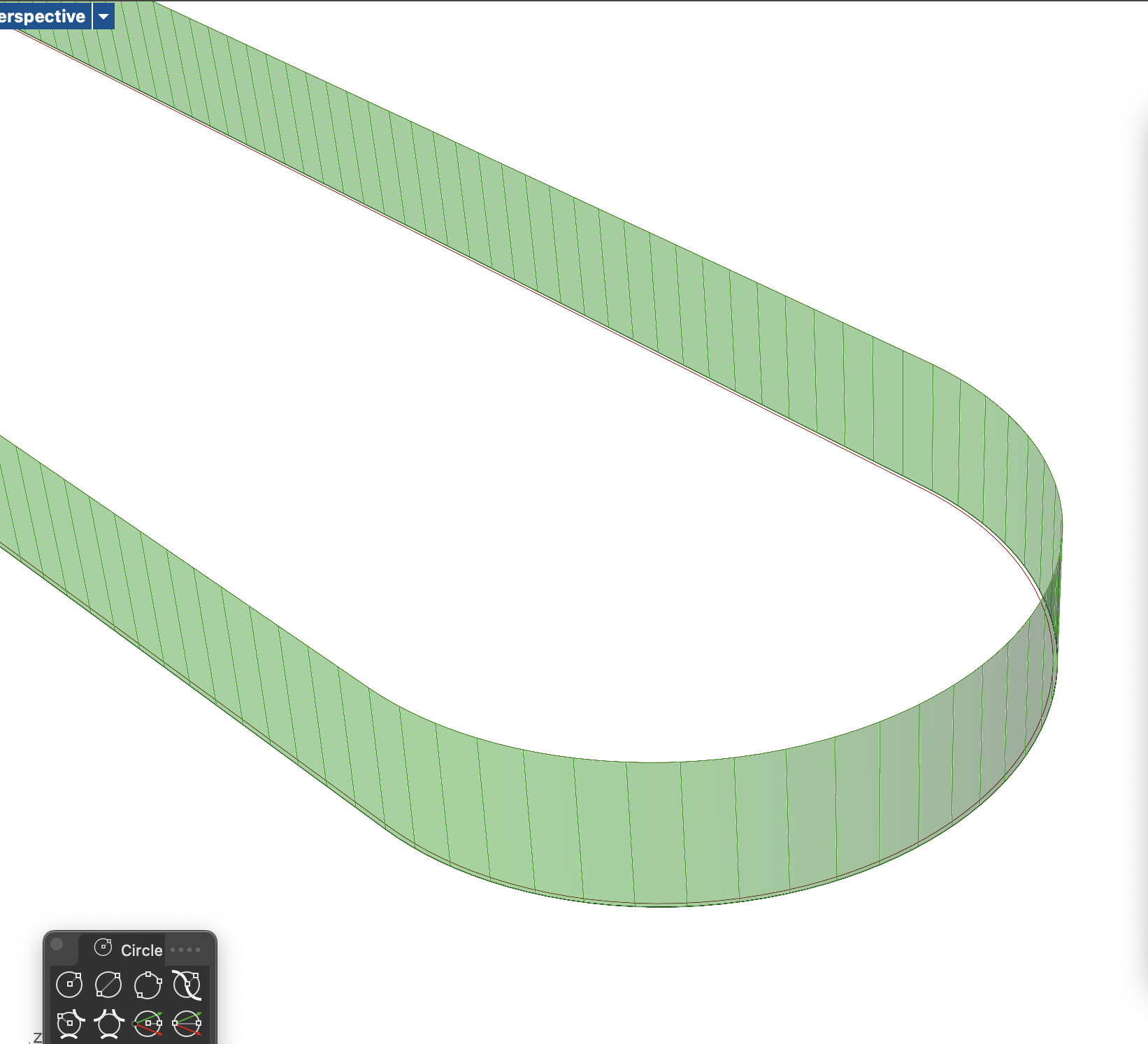
When I scale each panel in order to leave a small gap in between each panel, they are no longer aligned to their original plane as you can see here in the picture (red is original loft surface divided, green is the scaled one)
I apologize it was not clear, but I just want to keep the original division I created on the loft surface but scale each panel in only one direction leaving a gap in between of 10 cm. The only way I thought about doing this was through scaling NU
But there is already a gap because the surface fragments are rotated. And the fragments at each end or not flat (planar) because the follow the curve, so scaling them isn’t the same as moving an edge.
A gap aligned to the original surface, I do not intend to rotate them independently based on the center as the definition you shared with me. I want to keep their position and plane, I only want to create a small gap in between the panels, not by rotation, just by the width of the panel, meaning that if now 1 meter, now it should be 0.90 with 0.10 in each side for a gap
Rotate still works but maybe that requirement was another misunderstanding?
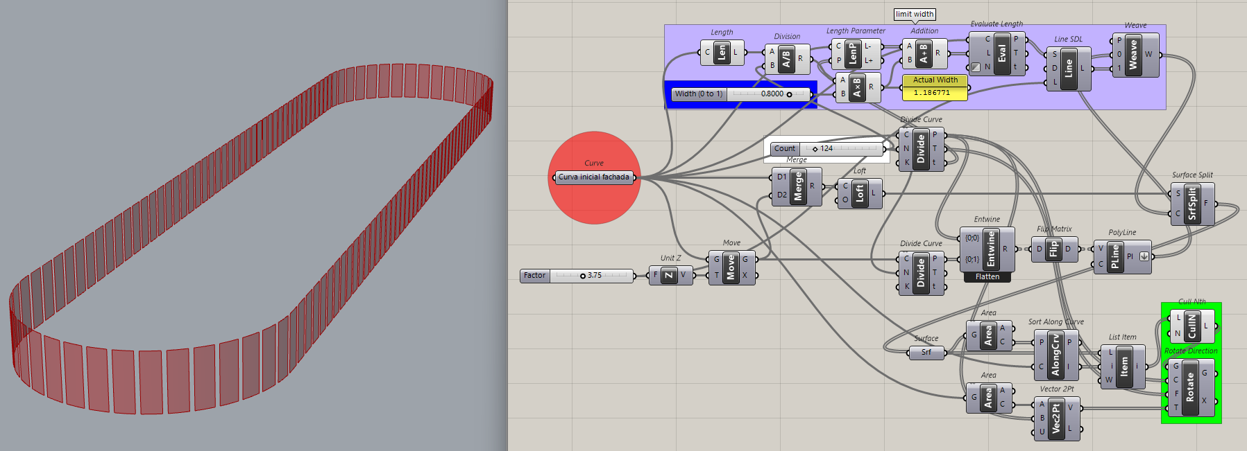
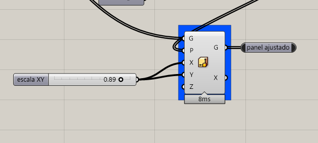
P.S. I modified the purple group so the ‘Width’ slider (blue group) is proportional (0 to 1), regardless of the ‘Count’ slider (white group). The ‘Actual Width’ is in the labeled text panel.
Rather than constructing a plane at the bottom of the surface you can evaluate each panel surface to find a properly oriented/aligned center plane from which you can scale in Y direction to create the gaps: