I first was exposed to and learned rhino way back when I was in grad school for architecture. That was version 4 and I was pretty competent with it. Upgraded to 5 and loved it but because I was beginning to learn and use Revit (something that is pretty essential for my work in the architecture field) I had less time to continue learning and improving my Rhino abilities. I think the gumball was introduced in 5 but I already had a workflow that worked for what I was doing and I didn’t bother learning how to use it. Big mistake I know now.
Anyways, fast forward 10 years or so and I have mostly been using AutoCAD and Revit because that is what I use professionally. I still use rhino (that is rhino 5) but usually just to model up some woodworking projects I am doing on the side. I am starting to use Rhino a lot more lately and really want to upgrade to version 7. I have an expired trial that I play with and I am now realizing how incredibly far behind I am as far as what is possible in rhino these days.
So, what resources have you all found the most helpful in learning rhino? Are there any online tutorials that you would suggest? I know YouTube has a plethora of videos out there and I use it all the time but which ones have you all found the most helpful over the years?
Any advice, suggestions, or whatever would be greatly appreciated. Thanks.
Also, make good use of this discussion forum.
When you can’t figure something out, or when you think you have, maybe come back, share what you’ve figured out, and hear how other people have cracked the same nut.
try to get a better understanding / perception of geometry.
This will help you mapping geometry to CAD/rhino-Workflows.
(visually) Scan / Analyse your everyday environment. For example while waiting for the bus, or while brushing your teeth…
A lot of everyday objects are simply composed of Extrusions and Solids of revolution - or a more or less complex combination of those…
Which are not ?
Which parts are more complex…
Compare old iron casted objects or early Bakelit plastic stuff with modern product design…
Where is the crux in those objects ? the overall shape or the details ?
Model a few objects that seem easy for you.
Model them a second time and enjoy, that you need 1/3 of the time.
And then, there will be some tasks that will make you suffer for a hole night or 2 days… I think this is normal part of the learning …
The manuals themselves are really good and include exercises that are both practical but also kind of fun to do. I myself really need to do the Level 2 to refresh my skills in a few areas. The Level 1 manual will have lots of overlap with your existing skills, but it’s a really good way to get back into Rhino (even though it was made for R6). I wish I had done both manuals straight away, but like you I got out of Rhino then back into it. When you know most of the fundamentals but are missing key skills in random areas, it’s harder to get the most out of a 1-hour video or a step-by-step tutorial. I’m filling in the gaps as needed but I recommend avoiding that approach if possible.
I would claim that modern objects are closer to what is easy to reach with CAD - which might (positively) result in a clear hierarchy - but maybe less creativity regarding geometry.
And older objects tell more about the collaboration between a good designer and a great craftman / model-maker - and have another level of graphic quality.
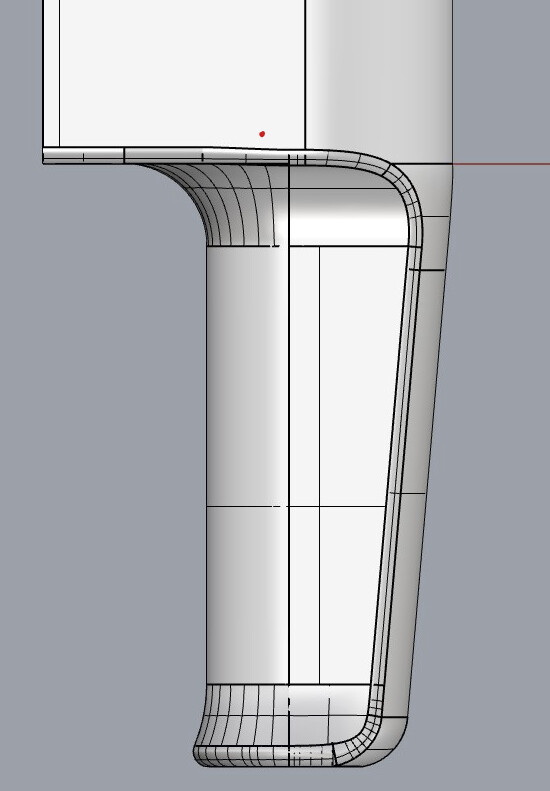
one detail i came across recently is the Braun 4402 hair dryer - one of my students worked on it
it is really a big deal to get this green fillet as precise as the original part - and i am quite sure there where many lime-(tree)-wood models to find the shape - i always wanted to fake some of those old models - two parts glued together and some precisely put filler - and i imagine a workshop, and the discussion between the designer and the model-maker… and they where driven by this very graphic perception. (which is great)
give a 2d-sketch of this object to young CAD-Modeller, tell the intent of this very graphic edge / small radius and for sure after 2 or 5 hours he will tell, this is geometrically not possible in 3d. Modelled with pure (circular / G1 / constant radius) Fillets it will look like this:
This is how I think it was made. Braun4402.3dm (537.0 KB)
Of course, in order to produce the same shape as the toolmaker, who created the mold for this part, one would need to have the same dimensions the toolmaker was given.
Talking about the times when resins were used here … don’t know if injected plastic object existed before, or how things possibly worked …
Long story short :
Mechanical drawings were made.
The model maker (reading the drawings) built the (wooden/resin) model, along with parting surfaces.
Resin was poured on the model to obtain a resin block shaped like the mold.
The ‘resins’, once hardened, were handed over to the mold maker.
The mold maker, using a copying milling machine, replicated the resin shapes onto steel blocks.
Etc …
Before they had ‘resins’, they had plaster for moldmaking. Plaster use dates back for millennia.
And, of course, many of the original wood master models (positives) were actually used as foundry patterns for sand casting metal. Inside fillets on the wood models were often applied using a hard wax and ‘radius balls’.
That brings back memories. When I started as an apprentice moldmaker over 40 years ago this is exactly how we did it. There was no CAD and not a single CNC machine. Our most “advanced” tech at the time was a CMM that used vacuum tubes to display the digits.
Yes of course you can see from the reflections how this was made. It looks to me that the whole thing is composed of tangent arcs. If we had the same defined dimensions for those arcs we could model the part in Rhino as accurately as it was done in the 70’s.
When this part was made, the part manufacturer didn’t know or care anything about G1.
Arcs were used to define curved parts because they create aesthetically pleasing reflections and because they were easy to define in 2d drawings. Remember there is an inside to this part that has to fit with both the outside (wall thickness) and has to fit with the mechanical parts inside.
Nobody can manufacture a G1 surface transition. In order to make a highly polished surface transition that would reflect light the same as it does on a CAD model would require a manufacturing precision to 1/millionth of a MM or better. Nobody can do that.
When the mold for this part was made it was polished to give the part a fine surface finish, but that was done by experts who knew how to preserve the aesthetics of the way the part was designed.