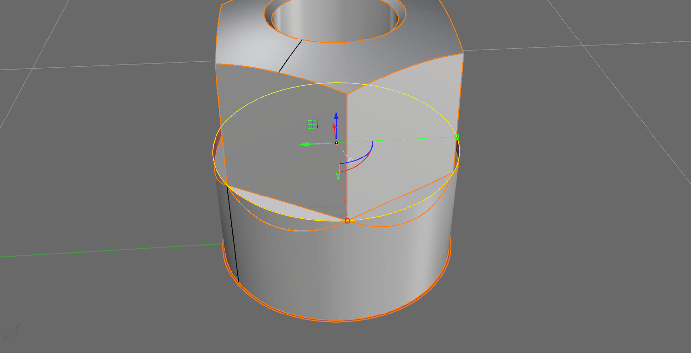
Ah, I didn’t really master the Project command (now realizing I could guide the project direction with mouse clicks). OK, the “§1 height” problem solved.
But the fillet width (pts 1 and 2 in your picture), how did you arrive at them? This fillet width didn’t “come natural” to me ( ), but I understand that a suitable location for 1 & 2 is important for the horizontal edge to land at in order to avoid distorting the continuity. But how determine location 1 & 2?
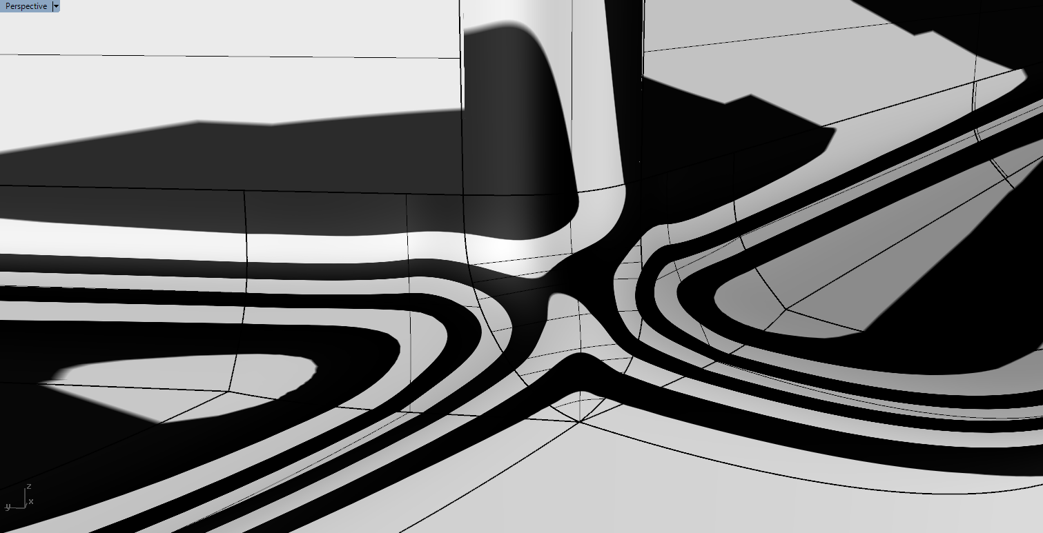
Yes it does affect but not that much.It depends on the situation. I’m trying to give it a smooth look. Edges should look relaxed. Like if you did a mesh relaxation. As said, I worked unclean there. I should have just created a blend curve “tan to pos”, creating a blendcurve with 3 points, creating a plane with three points and real trimmed the fillet at this plane. Instead I trimmed on the projected curve, that’s why its a bit wavy (last image). Anyway you can vary the location of the corners 1 and 2.
I would like to get some advice from @pascal@dan@John_Brock (or other McNeel boys and girls) on how to “fix” these fittings using Rhino Mac v5 (pending v6)
First if all, if this part were manufactured, the manufacturer would use rolling ball fillets. And you can make those fillets easily with Rhino
If you think of this as a surface modeling problem its quite simple. Fillets work best when you arrange things as two sets of tangent surfaces that you connect with fillets
In the attached file the objective is to connect the red and blue with a string of fillets. filletSrf.3dm (787.5 KB)
There is no need to trim the surfaces before making the fillets. I did that just to make it easier to see where to click when you pick each pair of surfaces that get selected to make each fillet surface, I used dupborder command to create curves used for the final trimming,
With regards to Rhino, you may have to wait for Godot. It seems to be all about architecture tools and rendering, not about delivering modern manipulation, control and analysis tools, even though patents of many algorithms are expired.
Like it or not the geometry is what manufacturers use because it produces the best results. You are complaining about a level of accuracy that is more precise than the typical manufacturing process can deliver.
That said, you can make it more accurate in Rhino. Enclosed is a file where I made all the connecting surfaces with filletsrf using a tighter tolerance. filletSrf2.3dm (232.2 KB)
well there is some truth in there. If you do 0.5 mm fillets, man who cares, unfortunate the people I do work for care no matter how small the fillet is. Simply because they can zoom in infinitely. Further more its also a matter of material and production accuracy. So yeah, sometimes its just satisfying the system. On the other hand, doing it right, isn’t necessary a slower workflow
Throw some sticks into the spokes of the mouse wheel so they can’t zoom in so far…
BTW, I’ve been working on the floor as a machine operator (both CNC milling machines and CNC lathes) and you will hardly find a CNC production machine with finer precision than 0.004 mm. And in a rotating lathe any polysurface edges across a cutting path will never become visible, not even by chance. When I later became manager in the company I forced - for good reasons - the engineers to verify their work by at least one blue collar worker from the “floor”.
Unthinkable in some cultures? Probably. But in the company I was responsible for productivity and quality it was misconduct, yes, plain breach of duty by the engineer (sub contractor machining shop) if not having the models/blueprints signed by a blue-collar worker - down at the floor - before releasing models or data for production. So many good reasons for that.
The second issue I found was the base radius was bigger than the intersecting surfaces in the middle part of the bolt, as a result the model had unnecessary surfaces making more difficult to fillet, blending. So you have to re-do that.
Out of curiosity, what does Xnurbs make of this example, if the surfaces have been suitably trimmed back?
Thinking about it, the need to trim back prior to commencing does play against Xnurbs in this case, as there is a fair bit of working involved in the trimming.
 ), but I understand that a suitable location for 1 & 2 is important for the horizontal edge to land at in order to avoid distorting the continuity. But how determine location 1 & 2?