Thank you Daniel, that’s exactly what I was looking for. And I find your Tray unfolding approach really interesting. Considering your recommendation, Is it possible to add the upper and bottom face to the structure at the same time and take into account the 6 faces of the box for the unroll?, in the code you sent you were considering just the 5 faces. and, Can you please explain me quickly what are you doing in the code just to better understand, I’m not too familiar with C# yet.
And just for the posterity, I found another way to unroll the 4 faces of the structure with the unroll component from open nest.
One simple way could be to generate it so the panels extend slightly below the ground plane first, then chop off the part below.
Because there’s only 2 panels meeting at these boundary vertices you don’t have to worry about the torsion free property like you do with the internal nodes.
If you want the panels around the base to be vertical, you could add direction constraints to the edges which have one end on the boundary.
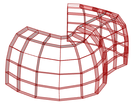
When I created this simple example and initially plugged it into conical offset (FaceFaceOffset) it does work, but when I increase of number of verticals and horizontals, it begins to break. I’m wondering if there is a problem with my method, that’s it’s not conical enough, or just not what the offset component is expecting.
I tried running the Monge through Conicalize and it does “fix” it to a point where FaceFaceOffset works but the edge boundaries are severely modified in the process.
When I use WeaverBird Offset Mesh it does look good but I’m still testing that and trying to sort the beams out to mimic the conical offset.
I feel like I’m close but not quite there, I’d appreciate your input. Piggy backing onto this thread because all conical posts inevitably point back here.
The mesh your file generates from this sweep is quite far from conical.
Here’s a file which measures the angles around each interior vertex. monge conical.gh (18.4 KB)
On a conical mesh, each vertex must satisfy ω1 + ω3 = ω2 + ω4 (where ωi are the interior angles of the cyclically ordered surrounding faces). This shows they are up to 0.23 radians off. There will always be some amount of numerical error here because of floating point calculations, but if the process is right you’d expect to see several orders of magnitude less than this. I notice the quads are also visibly non planar.
So I’m guessing something is wrong in your implementation of the construction process described in that paper.
I can give some more examples of how you can use Kangaroo to optimize non conical meshes to make them conical if it helps (and keep boundaries in place while doing so), but it is different to a constructive approach (which gives up a bit of shape freedom but simplifies the process).
Initially I was using a Sweep2 with Quad Remesh but the results were not as clean as the paper, that’s when I tried to construct my own mesh from lines and likely ran into issues. I would like to create an authentic Monge’s Surface.
That said, I am interested in your example that retains boundaries, below is the conicalize method I’m using which seems to work but wrinkled the top and bottom edge quite a bit. The bottom edge being the most important.
I’m somewhat familiar with the more restrictive methods, you have to work very hard to come up with an organic, asymmetric shape that sits nicely on the ground. The Monge’s Surface paper really excited me because it seems like a way to generate a conical free-form wall or walled-enclosure from just a few wavy curves.
I have been working recently in the conical mesh topic and I notice that after applying the offset mesh component from kangaroo2, to a conical mesh, the edges of the resulting beams structure are not planar so I applied a planarity optimization to this beams structure and now they are planar but the nodes are no longer centered on the original conical mesh normals.
I had the same planarity issues at the edges with different geometries after applying the offset component.
So I would like to know:
1.- Why the edges of the resulting beam mesh are not planar or if this is a bug.
2.- How I can obtain all the planar beams including those at the edges without displacing the node from the normals of the conical mesh.
I see you’re talking about the beams at the naked boundary.
The issue is that conicality is defined and optimised for here as an angle condition on the 2 pairs of opposite faces around a vertex, but the naked vertices don’t have pairs of opposite faces.
The way I’ve generally used it if I need beams for a mesh with boundary is to include an extra outer ring of faces in the optimisation, then discard them later. This way all the vertices actually used are fully surrounded by faces during the optimisation and offset generation.
(I find this general approach of using a ‘skirt’ during optimisation, then trimming it off after comes in handy for other types of mesh optimisation too)
Let me know if that isn’t a workable solution for you though. I think it would be possible with some small changes to optimise for naked vertices too if needed.
Thank you for your response @DanielPiker . That’s a great solution I’ll implement it in future projets. In the project that I’m working right now, its a bit hard to start again the initial mesh since it is some advanced. So if you dont mind to show me a way to apply an optimised versión for naked vértices it would be great also to apply in future projects.
Mirroring the question from @dannysantiagovi above as he’s been helping me with the conical logic since it was his focus in our grad program. This is the initial parametric prototype I put together, the parts fit together smashingly but I chose interior sections and manually modified the base due to cascading issues from the naked boundaries. The nodes ended up being irregular and not centered enough for utilizing bolts.
In effort to twist and contort various conical shapes to give more asymmetry, the perquisite skirts are somewhat limiting for form finding, especially on the ground plane which needs to remain relatively flat.
I thought I’d resurrect this topic, going on a year latter. The conical pavilion prototype was a success, I was very happy with the ease in which it assembled. Zero tolerance issues, except for when I had two pieces swapped. The node/beam data management and part labeling/engraving was crucial.
Ultimately we weren’t unable to resolve the naked boundary issue with FaceFaceOffset but followed @DanielPiker 's advice for adding a skirt and trimming it off. I have another opportunity to explore conical structures now and hope to push the conversation forward again.
Dear Daniel, I have an idea that’s been on my mind regarding conical meshes and isogonal molding surfaces mentioned in this conversation, and I would like to kindly ask for your help. The method of generating conical meshes with the conicalize component, as you mentioned, seeks to satisfy w1 + w3 = w2 + w4, but this method generates completely different angles at each node of the mesh. On the other hand, the method of generation isogonal surfaces is very interesting in terms of manufacturing and assembly due to having a high congruence of nodes, but due to its geometric construction, it is limited to Monge surfaces or surfaces of revolution. So I thought that by adding the angle goal, I could achieve repeatability of nodes, but when implementing it, I did not get the desired result. My question is, ¿How can an optimization be generated with Kangaroo that preserves the conical qualities and adds a high congruence of nodes in more complex meshes like a mesh with singularities. I would greatly appreciate it if you could add an example. And for that, I attach a file and images. I appreciate your kind attention in advance. Conical meshes.gh (305.7 KB)
In my experience, starting from a freeform mesh it’s very difficult to get many repeated elements through optimisation. You can try with EqualAngle, but I doubt it will be possible to reduce much the number of unique nodes without completely changing the shape.
I think if getting repeated elements is a high priority, it’s better to include some sort of translational or rotational symmetry from the start. For something like the mesh on the right in your image, you could use a Transform goal to keep 3 fold rotational symmetry.
Another direction to look at could be space frames where the beams are arcs.
Trying to get a mesh with identical nodes and straight edges is very limiting, but identical nodes and arcs as edges gives a bit more freedom.