Hello there!
Let me present first some scripting I’ve done over a couple of weekends. The idea is to use a curve to generate a turning-like toolpath for a 4-axis CNC machine. It cuts up machining time almost in half for revolved surfaces, compared to the way traditional, interpolated on mesh toolpath generation most CAM programs do. The bonus: this script translates the surface speed to the angular, moving slower on large radii, and faster on smaller. It looks kinda funky, but performs well, I tested it. Here is my brain-child (do not laugh):
Crv2GCode-v3a.rvb (3.4 KB)
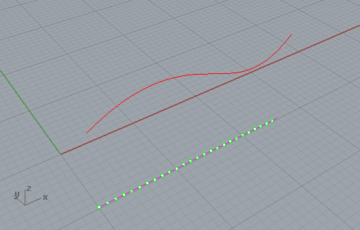
What needs fixing seems simple, but is not for me. The problem is with dividing (sectioning) the curve so it looks equally from orthogonal view. Sorry, missing the therm here, so I’ll use pictures.
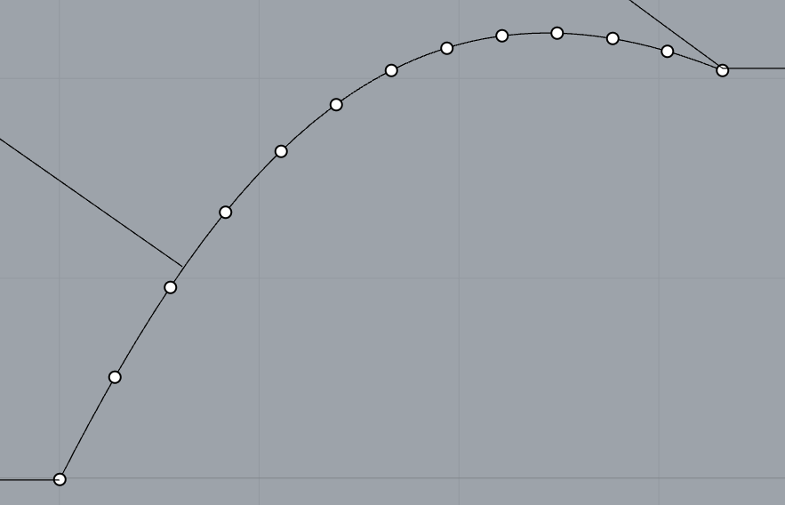
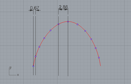
What the script does:
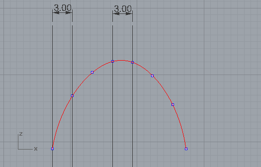
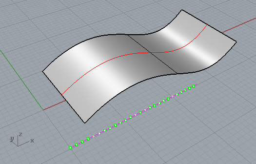
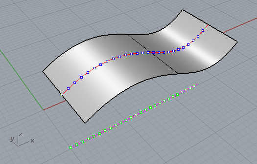
What it should do:
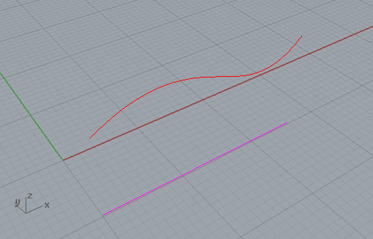
I would be very thankful if someone could script even a quick and dirty solution. I thought of something like projecting the curve to CPlane, dividing it with points, extruding the upper curve in a direction, perpendicular to projected on CPlane curve. Projecting the point back onto surface. To visualize it:

Thank you in advance for any input and critique.
-Vitaliy
Hi Vitaliy
( I cannot test what I’m going to say, sorry … no Rhino here … )
I think that if, at this point, you use the parameter values of these points to calculate the points on the original curve, you should get the points you are looking for.
I’ll try to explain ( My English is much worse that yours …  ) …
) …
You have a 3D curve, let’s call it A
Project it onto the CPlane obtaining curve B
Now divide curve B to get equidistant points P1, P2, P3 etc …
that have parameter values U1, U2, U3 etc …
( Rhino.DivideCurveEquidistant() can return parameter values )
OK, now if you evaluate curve A ( Rhino.EvaluateCurve() ) with parameter values U1, U2, U3 etc …
I think you’ll get the desired points.
( But, as I said, unfortunately I’m not able to verify that now … )
HTH, regards
I modified the example from the Contour Command, I think it gives you what you are looking for:
Sub Main()

	Const rhObjectCurve = 4

	Dim strObject, arrStartPoint, arrEndPoint, arrContour, arrPoint

	Dim sPoint, ePoint

	strObject = Rhino.GetObject("Select curve", rhObjectCurve)

	sPoint = Rhino.CurveStartPoint(strObject)
	ePoint = Rhino.CurveEndPoint(strObject)

	Dim deltaX, csp, cep, x1, x2

	deltaX = ePoint(0) - sPoint(0)
	x1 = sPoint(0)
	x2 = x1 + deltaX
	csp = array(x1, 0, 0)
	cep = array(x2, 0, 0)

	arrContour = Rhino.CurveContourPoints(strObject, csp, cep, 12.0)

	If IsArray(arrContour) Then
		Rhino.AddPoints arrContour
	End If

End Sub
Tom
Thank you, Emilio and Tom. That’s great! It will take a while for me to process it, and come up with some general cases. I’ll post the updated code later.
If you decide to use Python instead of VB (which was my old favorite), here is a similar version in a Python script:
import rhinoscriptsyntax as rs
c = rs.GetObject("Select a curve")
s = rs.CurveStartPoint(c); e = rs.CurveEndPoint(c)
deltaX = abs(e.X - s.X)
n = 12. # Set this to the number of intervals you want.  The number of points is n+1
arrContour = rs.CurveContourPoints(c,[s.X,0,0],[e.X,0,0],deltaX/n)
rs.AddPoints(arrContour)
What we found in getting the best results for making curves to gcode in grasshopper is by converting curves to polylines with straight sections and then extracting the control points.
I see that Rhino has a convert command which does the same so maybe you can use that in VB? Don’t know anything about VB myself.
All right, fixed it.
CrvToGCode.rvb (4.5 KB)
Just drag and drop it in an open Rhino file. The commands are either Crv2GCode or CrvToGCode. It is for 4-axis along X or Y, but is easy to convert to simple linear moves (just delete all the rotation code).
I wish #RhinoCAM and #MadCAM developers added this possibility to their 4-axis strategies list.
Thanks for replies!