280+ posts but more than half of them are from just 10 people…
jus’ sayin’…
2 Likes
Being one of the most progressing topics in a short period of time means that the discussion is very important for the Rhino users who demand for better tools that could make their work quicker and easier. ![]()
For example, Alias has an optional “Explicit control” inside its main modeling tools which is a huge advantage when it comes to surface quality, control over the general shape, time and ease of achieving G2 curvature continuity by adjusting far less control points subsequently. This option alone saver several commands that are other wise mandatory in Rhino to achieve similar results, such like: “Rebuilt surface”, “Rebuild surface UV”, “Change degree”, “Remove knot” and multiple use of “Match surface” after some of those commands. Imagine how powerful the “Blend surface”, “Match surface”, “Sweep 2 rails”, “Sweep 1 rail” and “Network surface” would be with an “Explicit control” option!
Static Zebra and coloured light lines that both Alias and VSR have are self-explanatory. They let the modeler examine the surface quality of the model from various angles without losing track on the stripes that stay the same (unless they are manually rotated via the dedicated handle).

User-friendly control point modeling via handles next to each selected control point is yet another HUGE advantage of Alias over Rhino. In Rhino, control point modeling is done in a slow way, and instead of using handles the modeler is forced to use rather non-intuitive tools such with no direct UI elements on the geometry itself. Also, the drag modes are inconsistent. For example, the “Control polygon” drag mode will not lock the direction of editing, leaving room for errors due to the fact that the selected control point(s) could be moved in some RANDOM direction, as well.
Activating the “Control polygon” drag mode does not automatically hide the Gumball, forcing the user to do that manually. If you try to drag a control point in this particular drag mode while the Gumball is on, you end up with dragging with the Gumball instead. Which is not along the control polygon, despite the selected drag mode that was supposed to lock the directions of dragging.
Lack of simple to implement U and V markers on the edited surface (also, showing up to the target surface(s) while using certain commands such like “Match surface”) forces the user to guess which direction is U and which is V. I’m aware that you can set custom colours for each direction, however, the “Rebuild surface”, “Rebuild surface UV” and the “MoveUVN” tool use U and V letters while the actual surface in the viewport don’t. Letters are far easier to recognize instantly by the majority of people. Also, the tiny coloured lines representing the U and V directions upon selecting a control point lie directly on the highlighted control polygon, making them even more difficult to distinguish, especially on 4K resolution and for colour blind people. The UV markers should be customizable in both, size and colour.
With UV markers:

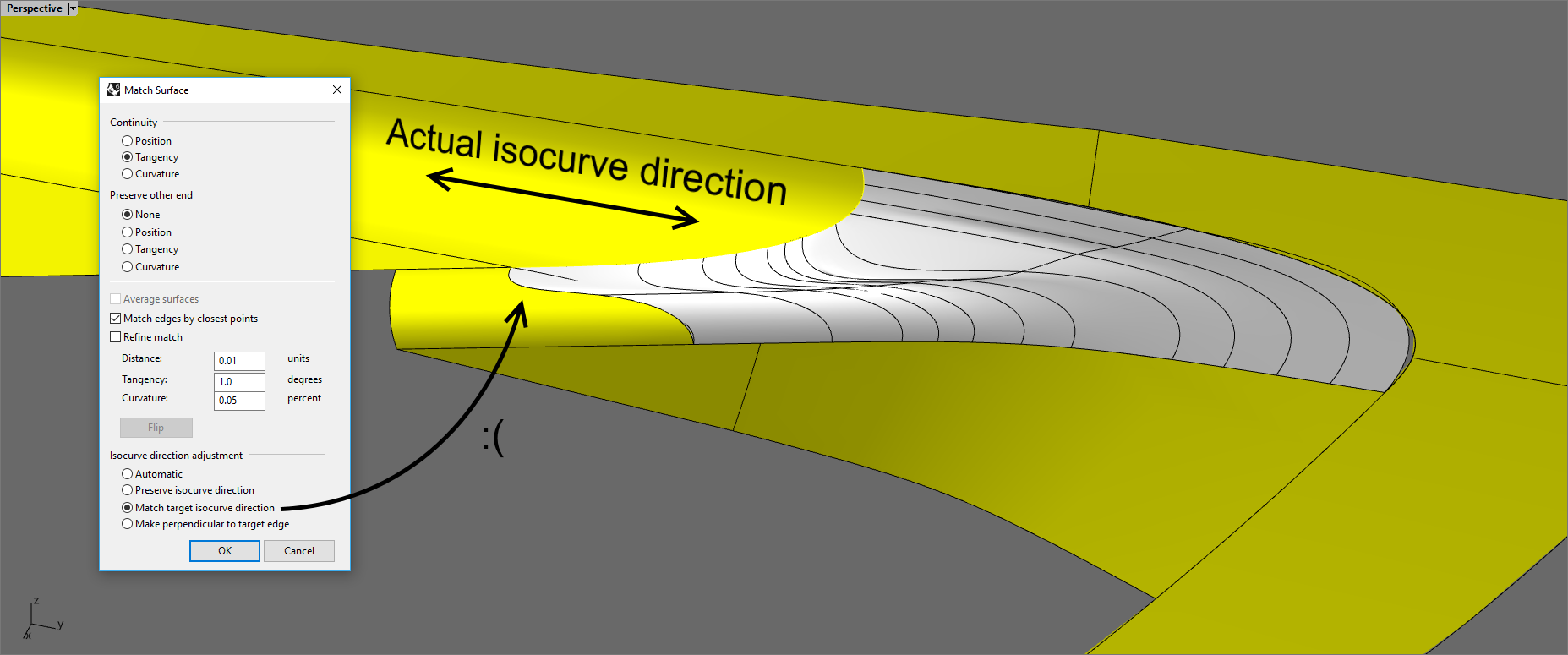
Also, an extremely huge disadvantage of “Match surface” is the inability to set either U or V isocurve direction to match to the target edge, as shown here:

A similar issue is found in the “Blend surface” tool which does not have an option to align the end handles to the target surface’s side edges (even on trimmed one).


11 Likes
Great Bobi! ![]()
1 Like
Hi Bobi, you have generously shown everyone on this forum your modeling skills and help people through modeling problems. That is great!
If you had to pick just one of the suggestions you have explained, which one would you choose? Which one would do the most good for you?
For me, it would be the explicit control with the directional markers at the control point selected. That way the Move UVN could be thrown away , because it would be integrated into the control point selected.—-Mark
2 Likes
I can’t pick one of those since at least 3 or 4 of them are essential for improving the modeling workflow.
“Explicit control” is really important, because it eliminates the need to use multiple tools after the surface creation in order to get an acceptable result. “Blend surface” and “Match surface” will benefit most from this option when it’s implemented.
“Control point modeling” via arrow handles directly around the selected control point(s) is another hugely important feature that’s missing in Rhino at the moment. But those arrow handles should let the user use two different drag strengths, as I showed in one of my images in the topic, because certain adjustments must be really small. It would be too time consuming to constantly change the drag strength manually each time. This is why, using two arrow handles for each direction is the better way to execute it (one arrow uses the global manually activated drag strength, and the second arrow is always set at 1% drag strength for precise adjustments to achieve G2 continuity while using the “Zebra analysis” or the “Edge continuity” tool).
Static Zebra helps with figuring out and fixing the imperfections of the model, so everyone will benefit from using it, no matter which industry.
“Patch” must be as good as “X-Nurbs”. Solidworks, Catia and all major CAD programs have much more powerful patch tools than Rhino. I use “Patch” only 2-3 times per year, because it capabilities are quite limited.
“Fillet edge” is very important for many Rhino users, but it’s also quite limited and fails in nearly every occasion when I use it. This is why I rarely rely on it and instead replace it with manually trimming the surface edges via pipes and then fill up the space with “Blend surface”.
6 Likes
@jordi.rovira - can you please post a simple example that approximates what this would do, even roughly? I guess it would be mostly useful if the target is a surface and not an edge, correct? Does the vector apply to all edges being matched, if more than one, or it it set per edge?
-Pascal
Hi this will be one of my first posts here.
It is really interesting for me, that this topic got so much attention.
I work 11 years in automotive (Alias Surface, Icem Surf), and I use Rhino since university for my hobby projects (so cca 15 years).
From my experience - Rhino is nowhere close to be seriously used in automotive for modeling (but we use it for file translation and for Grasshopper - to be honest - lack of high quality modelling capabilities brings us many times headaches in Grasshopper as well).
BUT, there are some tasks and fields, where Alias and Icem are “overkill”, but Rhino is still not on the level, where it can be effectively used - those are for examples design of tractors, trams, trains etc.
I think that is the field, where Rhino should aim with its toolset - not to cars (that is target too far right now), but something like “sub-automotive” field, where high level of direct modelling is asked, but not-so-ultra-high.
Only like 1/10th of the toolset of Icem would be sufficient for these cases.
What is needed to update most for those purposes was pointed out earlier, so yes, it is:
- control point movement
- match
- blend
- trim
- deviation analysis
- highlight analysis (btw - that is must have also for serious SubD modeling, should be added independent on other tools. We wanted to use Rhino SubDs for early stages of car design, but without showing highlights, it is not really useful)
Martin
6 Likes
Good morning Pascal,
I use this function to surface edges and projected on the surface as well.
I can show you a example how is applied in both cases.
To the edge (preview):

In Z(result):

Normal direction (result):

You can see the diference what happens between these two examples (in normal the row is wavy).
For me mostly in blends and fillets, need to have a specific direction to avoid unexpected results.
I think is because the big difference of the distance between rows in each surface, where the impact when matching is more unpredictable. But I am not a math expert.
Also projection onto a surface (with blend option activated,so all the control points are translated in the same proportion) :
Preview situation:

To Z:

The advantge of this is when projection a surface onto another from a vector, is that you preserve exactly the same shape from the view you projected, and it can be very convenient in some cases.
Regarding to being applied to all edges at a time, I have never used this kind of matching, I prefer to go one by one manually. (I checked it and icemsurf doesn’t have vector projection in the multi-matching function, only normal.)
If you need another type of example, please let me know.
Jordi.
@jordi.rovira - thanks - so the movement of the control points to achieve the desired continuity is constrained to the axis. I can imagine this might compromise the results in certain cases, correct?
If it is not too much trouble, having example surfaces - input and result for an axis constrained case - would be helpful.
-Pascal
The ability of each control points to move closer to or away from the edge is generally needed to exactly match curvature along the entire edge, not just at a few points. This was discussed in Wish: More options for "Match surface" - #16
Yes, but with feedback as to how far out your match is to perfect, you can make the decision to increase the order to get an acceptable match. The matching tools and analysis definitely go hand-in-hand.
3 Likes
Yep, feedback is a prominent area in our discussions here about how to make this all better…
-Pascal
4 Likes
Hi Martin, I’d be curious to get your opinion on the plugin I have been developing (Global-Edge-Continuity on PackageManager) and how it compares to the tools you are used to work with.
Hi Pascal,
Here I attached an input to see how the matching projected in a vector behaves (Z in this case):
Matchsurface-input.3dm (98.6 KB)
Also I think would be nice, not only to constraint the direction to the origin axis, but depending of your need, to Cplane or to the current view.
Yes, in some cases may happen that, but you have to have a good judgment when apply it or not. I mean, maybe is a base patch problem, not having enough degree or the direction you use is too compromised…
But in general terms it is very useful and convenient, mostly when you are rebuilding geometry.
Jordi.
2 Likes
Hello Gijs,
thanks for your work, I’m not sure I will be able to test it soon (at work we have older SR of Rhino 7 and at home I have Rhino 6)
From the pictures I have seen on the forum, it seems, that your plugin represents basic functions of Icem Surf “Matching Analysis” and “Surfaces Check”.
“Deviation analysis” is more about Curve-to-Curve (but also Edge-To-Edge), Curve-To-Surface.
I know some of these function are somewhere in Rhino, it is just somehow not comfortable to use it.
But yes, in the end it is not about how it is named, but if it has logic and is easy to use.
One thing I also forgot to mention - if there will be some changes to control point movement, please add those changes also to SubD modelling - there the possibility to move points on tangents etc. is also missing a lot.
I can compile the next for an earlier version, what’s the version you use?
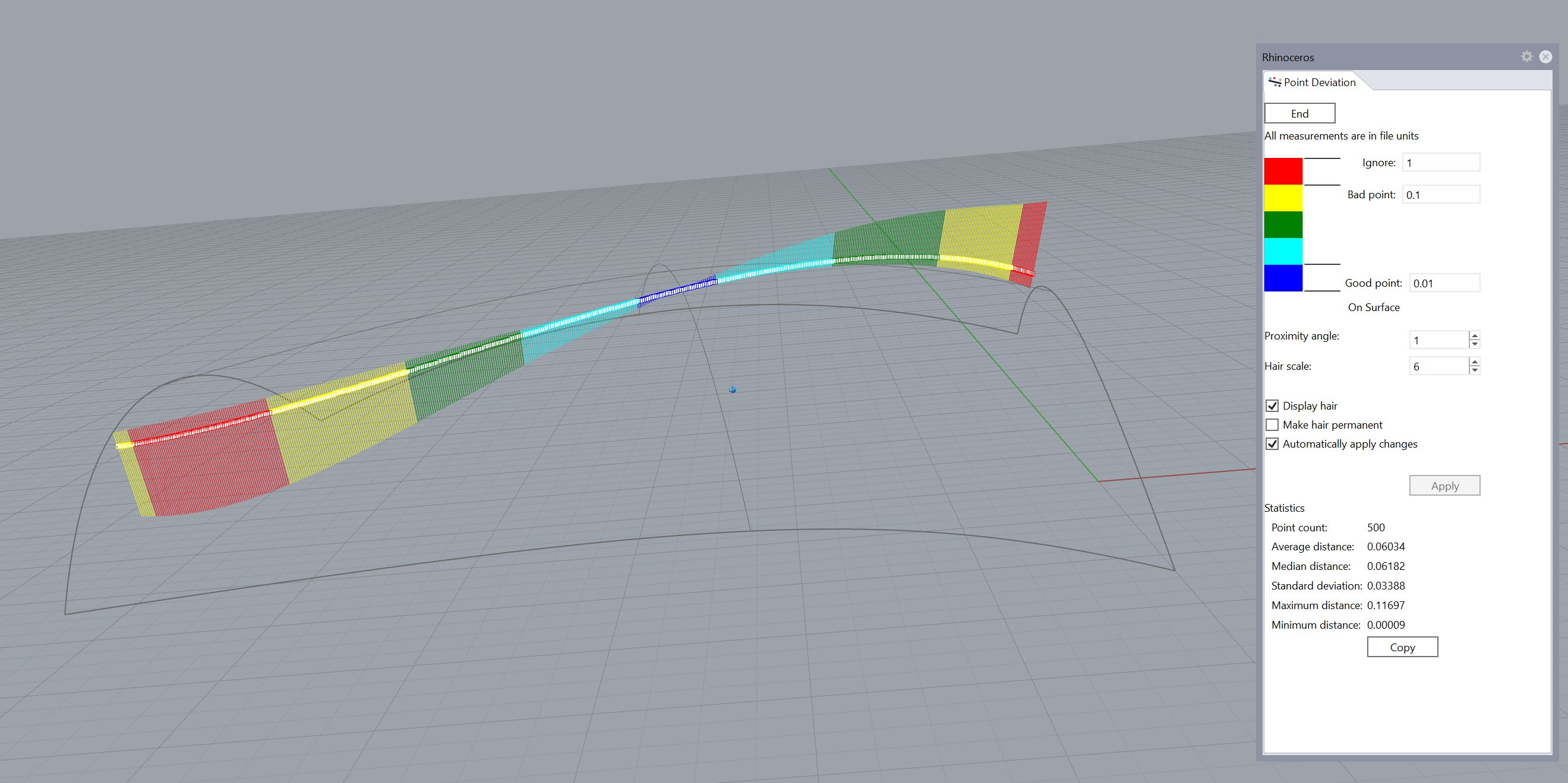
PointDeviation can be used for deviation of a curve from a curve, a curve from a surface, and a surface from a surface. It provides statistics and a graphic display, and updates as the curve or surface is modified. For me it is easy to use.
Enhancements I’d like to see are:
Selection of edges as “curve” for both objects to extract points from and objects to test,
Direct control over number of test points extracted from surfaces.
To use PointDeviation for deviation of a curve from a surface:
PointDeviation
Select the curve(s)
Enter
Select the surface
Enter
PointDeviationExample01.3dm (1.7 MB)
3 Likes
@Pascal created a plugin which appears to be a great tool for checking distance deviations. I have not tried it yet. CadWorx previously posted about it in post 96 of this thread.
@jordi.rovira - thanks, very helpful.
-Pascal
1 Like