I’ve been working on this for over a week - reading docs and help, watching videos and searching here. Part of my challenge might be in using the correct terms for searches and features in Rhino but I’ve tried enough combinations that I think I should have found something!
I’ve used Rhino for years but primarily for creating models for milling in metal and 3D printing. I now have a CNC router (Onefinity Journeyman ELITE) and want to convert images into wooden plaques, etc. I use Vectric VCarve Pro for the CAM side of things. However, Vectric have their much higher end Aspire product that includes tools for 3D design. One of the things it does very well (simply) is provide tools and a workflow for converting images to machinable 3D bas reliefs. In fact, one of their v11 video tutorials does exactly what I am trying to reproduce in Rhino - see https://www.youtube.com/watch?v=mH-o-LpA1gs
So far, I’ve tried a number of different approaches from using the new Rhino 8 UV Editor to creating the “form” of the trout either in a surface, mesh or SubD by drawing over the trout as a Background Image and converting this same image into a Heightmap as a SubD or surface. I’ve not been able to apply this height map to the form successfully. I’ve also not been able to align the trout image in UV Editor over the form successfully. I’ve also looked at (tried demo) of RhinoCAM Art module. It is very complex and very little information outside of a video from MEC Soft (i.e. no user contributed videos or tutorial). And I have used Blender for mesh work in the past so I took a look at it and pursued a lot of videos, etc. It doesn’t have features like Sweep 2 Rails that make the form side of things easy.
I would really appreciate a little direction on how to go about this in Rhino. Here is a screenshot of the attached 3dm file with some of my experimental attempts. I’d like to understand how to do this in Rhino as a baseline for more complicated things I have in mind that I don’t think are possible in Aspire. I have installed the Aspire demo and repeated the trout modeling demo from the video and it was remarkably straight forward - but I am sure that Rhino has the ability to do this, its just that there is SO much other functionality since Rhino is more general purpose.
Note: the form I made (surface) in this file is over simplified for this post. I can create a much more realistic form with fins, etc but didn’t want to overcomplicate my root question.
I should add that I did spend a lot of time studying the Rhino 8 video on Texture Mapping with the UV Editor (https://www.youtube.com/watch?v=uAj0qK6x6xk&t=238s) I ran in to difficulty in a few areas - firstly, the image I brought in came in upside down and reflected. Also, I was not able to align the image over the form using the guide vector approach (I am not sure how to use this feature). In the video the vector outline was created in photoshop and saved as an ai. I tried to do this using vectors I drew in Rhino over the bitmap background image but could not figure out how to get them into UV Editor.
hm, looking at your video i think what you could get away with shrinkwrap (new command in v8) to skin all that puzzle pieces together. that would at least be pretty fast. then conver to a subd and finish it off.
for this to work you need closed geometry, so mirroring your loft maybe increase the z height a bit from his then cut it in seam to join it nicely together. then add fins extrude them and use shrinkwrap. its still a little fiddly but will save you a lot of manual work.
Thank @encephalon - the “Form” surfaces in the file I attached are 3 separate pieces but I’ve joined them to create one surface and I have actually used the new Shrinkwrap to create a subD as well. I know how to add the fins and tail shapes using subD - I left those out on purpose to simplify the problem I’m trying to solve - how to get the “texture”/“height map”/“displacement” from the trout image on to the surface (or subD or mesh).
Yeah, I’ve tried that too. The thing is, I have tried a lot of approaches and each one gets hung up at some point. In this case, I can’t align the weightmap surface with the trout form surface properly.
This is why I am confident that Rhino can do what I’d like but the devil is in the nitty gritty details! I can’t find a complete end-to-end path to produce the desired output.
more precise:
I would do some initial modelling with subD. (as in the screenshot)
on top if it apply heightmap
or a displacement and extract Rendermesh.
faster and a bit bricolage:
Instead of doing a single SubD you could also build an initial SubD, (the fish body)
build the next SubD (the gill ) and just pull it to the first.
modify / shape it.
build the next SubD (the eye) and pull it to the second (the gill)
shape it
use additional elements nurbs and meshes to build the initial shape…
as soon as you have all those layers of shapes shrinkwrap it.
maybe quadremesh for nicer mesh-typology.
do a final displacement or heightfield for the tiny details.
both approaches are inspired by the video you linked.
but you might miss some mesh / voxel based sculpting tools in Rhino. (you ll find them in blender for example)
Thanks Tom. Yes, I know how to make the shape of the trout (or anything else) using the methods you describe. Keeping the parts separate and then doing a shrinkwrap over everything is a great tool - I can reuse various components like eyes, gills, fins, etc on other models.
My issue comes down to how to put that height map on the form - the is where I get hung up. I’ll try an approach - do lots of research and some simple experiments - but then when I proceed on this project things hit a wall. Either the image won’t line up with the form, or it will be mirror imaged and won’t align, or … It is driving me crazy!
I use the paper doll technique to create the subD like this. Components added individually afterwards (like the eye). This works well. Now to figure out the texturing to add those subtle details, that’s the struggle.
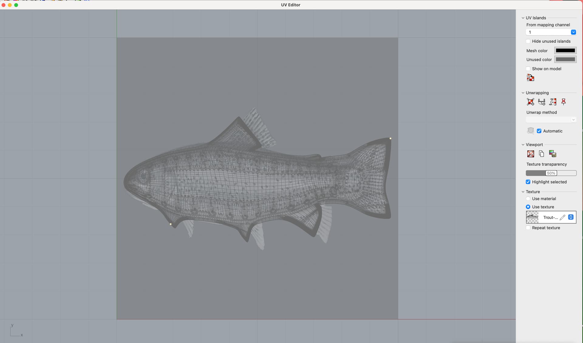
Here is what I get when I try to add the image as a displacement map and opening the UV Editor.
So many little surfaces from what is a single subD surface. Also note the trout image is rotated 180° so it is upside down. It would be great to have it rightside up to make it easier to work with.
Yes, I have tried that. Here is the results. And when I look at this in UV Editor I get the image I posted above with the surface being broken down into many small rectangular areas. This is a subD - is that the issue, should I convert to a mesh first.
EDIT: I converted to a polysurface and then tried the displacement and get the same results.
@Tom_P I’m getting closer! I created a polysurface from the subD and then applied a displacement. I then used Unwrap and selected the profile edge of the trout shape in the unwrap as shown in the screen capture. Then, opening the UV editor the image and trout are correctly oriented (no idea why it worked this time but it did). I had to move the unwrap to fit over the trout image and scale it a bit to get the second screen capture. So now, I’d like to get the edge of the Unwrap to match the edge of the image. I saw videos and read about using a vector outline but I have not been able to get that to work - I can create the vector (curve) outline in Rhino but can’t get it into the UV Editor.
Ok, making some progress. I am able to create vectors in UV Editor and align the curved edges of the mesh to them. I did the top, bottom and end of tail as separate alignments and they look great to me. Now the issue is one that I’ve been fighting for days - the image in the UV Editor and the mesh are oriented properly but the image is flipped upside down in the main window. Here is a screen capture that shows it all. I have no idea how to fix this.
I should add that I am going back and forth between Mac and Windows just to make sure I’m not running in to an issue on one or the other. So far, the behavior is identical on both platforms.
Yeah, I will back off the detail once I figure out how to do this. I’ve cut similar sorts of models that I’ve downloaded and they turn out really nice. That’s why I want to make my own.