Rhino to Cutter: A Vinyl Cutter/Plotter Revival Story
Hi everyone,
This is the fourth post in my ongoing retrospective series, sharing long-form Rhino + Grasshopper development projects from the past decade.
Today, I’m staying within Rhino, but shifting focus to code development using Python —specifically, writing a custom print driver for a long-disused vinyl cutter/plotter.
 Project Summary
Project: Rhino-to-Vinyl-Cutter Workflow
Client: Internal R&D / Workshop Automation
Timeline: Oct 2017 – Dec 2017 (initial build; still in use)
Tools Used: Rhino 6, Python (RhinoScriptSyntax, pySerial), Hyper-Terminal
Deliverables:
Lines of Code: ~150 (Python)
 From Circuits to Cutting: A Long Loop Back
Although I’ve worked in the water sports and kiteboarding industry for over 25 years, my background is in Electronic Engineering. In fact, my final-year university project involved controlling a DOS-based MP3 player via the serial port — a niche challenge at the time (many many years before the first iPod), but one that got me comfortable with direct hardware communication.
I had no idea that 20 years later, that same experience would become the foundation for solving a very different problem.
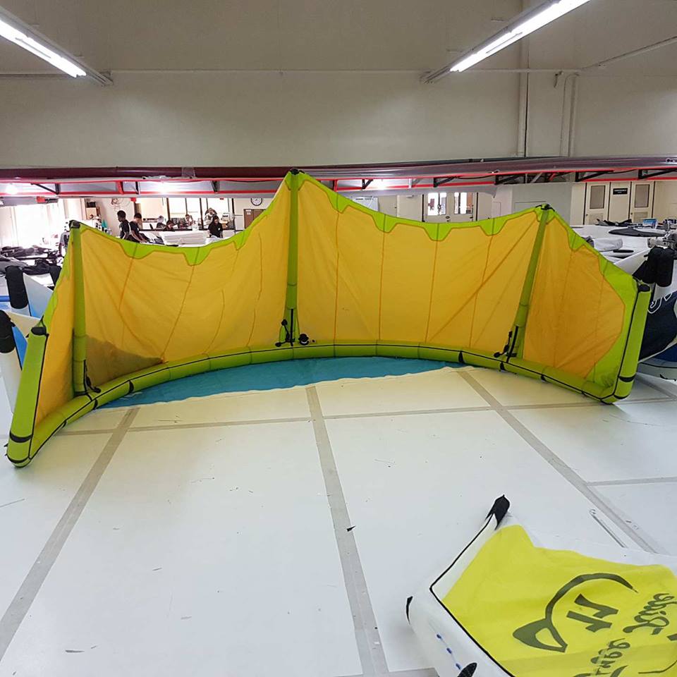
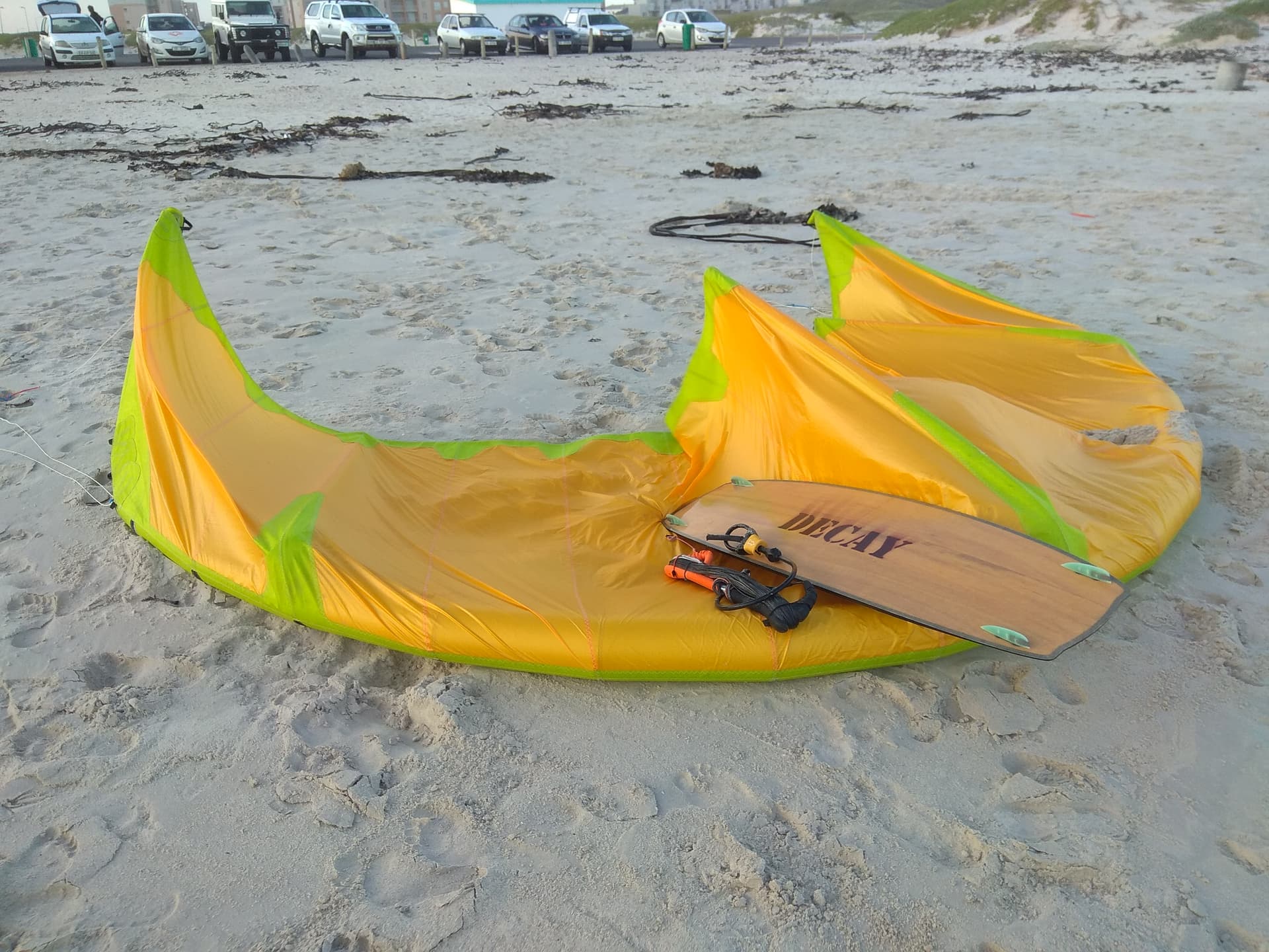
By 2017, I was working in and around the Airush Development Lab in Cape Town — building prototypes, developing custom tools, and setting up the workshop for lean, digital manufacturing. One of the tools I needed was a vinyl cutter — not just for logos and decals, but for spray masks and full-size pattern plotting.
 Right Place, Right Time… Right Machine
As luck would have it, Dave Stubbs, the legendary Cape Town surfboard shaper, was working in the space next door. One day, I mentioned I was looking for a cutter and he casually remarked:
“Oh, I’ve got one in storage — just around the corner.”
That offhand comment led me to an old DGI OM-60, long unused, sitting just a few meters away.
I took the cutter home, gave it a deep clean, and powered it on. It passed its self-test flawlessly. But there was one issue:
The software was missing — and long discontinued.
 The Hidden Treasure: A Real Manual
There were no drivers. No install disks. And no support from the manufacturer.
But being so old had one big upside: it came with a proper manual — thick, printed on paper, and full of command documentation, including HPGL syntax and serial port settings.
That manual became my gateway. It made one thing very clear: if I could speak HPGL, I could control the machine.
So the question became:
Could I drive this cutter directly from Rhino?
 GitHub and Grasshopper: A Starting Point
A quick search for “Rhino HPGL” turned up a GitHub project doing just that — or at least part of it. The script converted Rhino curves into HPGL commands and saved them to disk.
The code was in Python, a language I had never used before — but it was clean, readable, and I quickly understood the control flow.
I gave it a spin and soon had my first HPGL files saved to my drive.
But I still needed a way to send them to the cutter.
🖧 Old Tricks Still Work
This is where things got interesting.
It turns out that Windows 10 still supports old DOS-style commands to pipe files directly to legacy printer ports. I gave one of them a try — aimed it at LPT1, and hit Enter.
To my shock, the machine came to life.
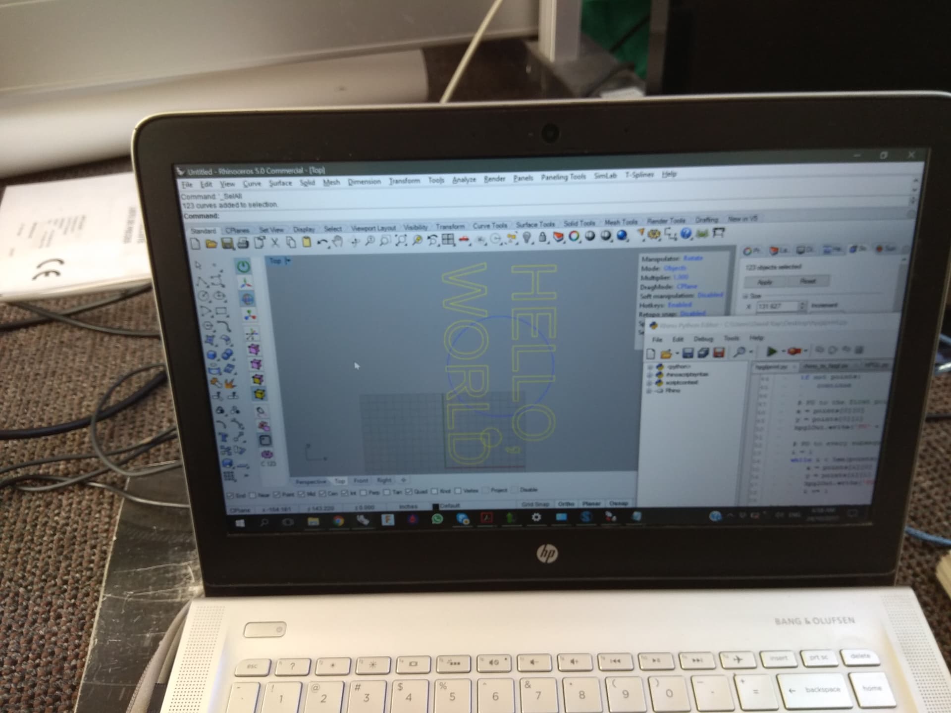
I loaded some paper into the cutter, wrapped masking tape around a felt pen, and jammed it into the empty blade holder. And there it was — the cutter began plotting “Hello World”!
But not perfectly.
The curves came out fragmented — plotted as disconnected line segments instead of smooth paths. Clearly, there was room to improve the HPGL generation.
 Digging Deeper: RhinoScript + Python
To fix the jagged plotting, I dove into the RhinoScriptSyntax documentation and started refining the conversion process.
Rhino has a deep SDK and excellent curve tools — I just had to tap into them. With a few changes, I was able to smooth the output, preserve closed curve logic, and still generate valid HPGL.
From there, the results improved dramatically.
 Real-Time Plotting: Let’s Talk Serial
With clean HPGL output sorted, I wondered:
Why not skip the file export entirely?
The cutter had a serial port — could I send commands directly from Python in Rhino, without writing to disk?
To test this, I needed a USB-to-Serial adapter (since no modern PC has a COM port anymore) and, as the manual specified, a null modem cable to properly cross the TX/RX lines.
A quick trip to the electronics store and some soldering later, I had a working cable setup.
 Terminal Test: The Moment It Talked Back
Just like I had decades earlier, I fired up a terminal emulator and aimed it at the new COM port.
A few HPGL commands type in… the machine replied, returning the current paper dimensions.
That was the moment. We weren’t just sending commands — we were having a conversation.
 Python Makes It Easy
This is where my real appreciation for Python began.
Using the built-in pyserial library, I was able to set up and control the serial connection with just a few lines of code. The integration felt natural, and it slotted right into my existing HPGL script with minimal effort.
Within an evening, I had live Rhino-to-cutter plotting working — no file exports, no shell commands.
 Polishing the Tool
Over the following weeks, I began adding more logic:
- Querying the maximum plot size from the cutter
- Ensuring only closed curves were sent
- Adding user prompts and simple error checking
Python made these improvements feel easy, and Rhino’s script interface made integration painless.
 From Scrap to Shop Floor
What started as a dusty old machine — seen as scrap by most — became a workhorse in my workshop.
This revived cutter has since handled hundreds of jobs for me (and for Dave Stubbs too). From logos to layout templates, it became an everyday part of my #digitalmfg toolkit.
More importantly, this project reminded me how past experience, a bit of curiosity, and a willingness to dive into the unknown can unlock serious value — both in tools and in learning.
 The First of Many
This project also marked a turning point for me — the first time I wrote code inside Rhino to directly drive a machine.
It laid the foundation for a new kind of workflow: one where design, logic, and fabrication are tightly integrated through custom code.
That same mindset would eventually lead to more ambitious projects like Shapewave WAM and KaroroCAM — but those are stories for another time.
Thanks for reading — happy to dive into the Python/Rhino side if anyone’s curious, or share the repo if there’s interest.
David Kay
KaroroCAD • KaroroCAM • DKUI • DGRS Stack
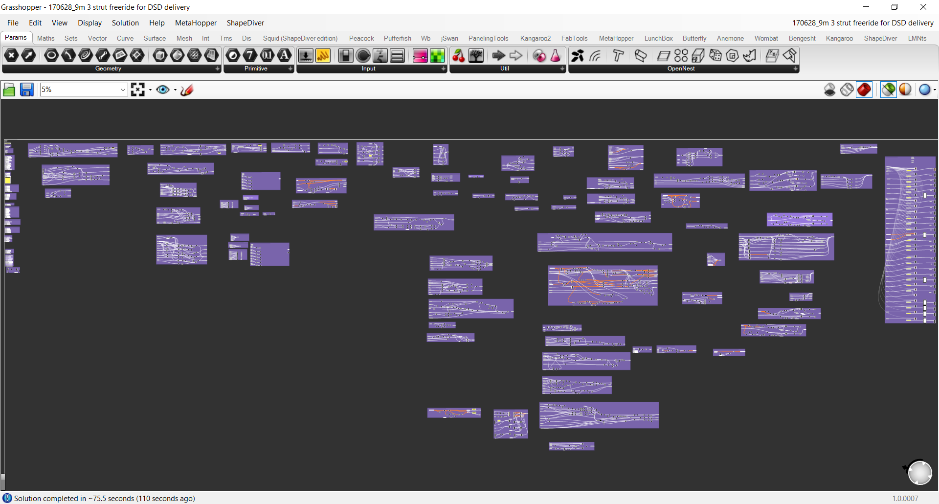
In the thick of development
Will this work?
Pen Plotter
Everyone LOVES their own stickers
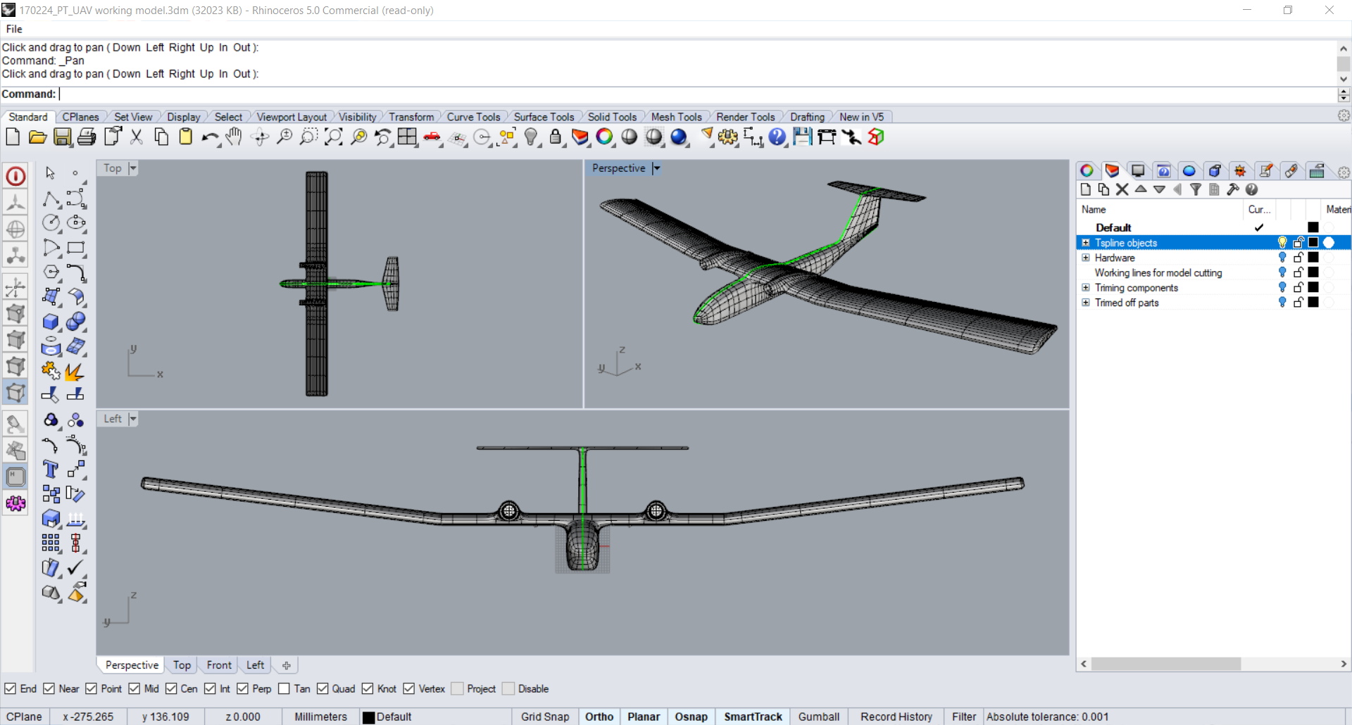
 Project Archive: Composite UAV Drone (2016–2017)
 Project Overview
 Project Brief