How to fix it in grasshopper? I added Grasshopper file where i have 3 mesh needed to combine and create volumetric 3d mesh

unnamed.gh (159.2 KB)
How to fix it in grasshopper? I added Grasshopper file where i have 3 mesh needed to combine and create volumetric 3d mesh
After locating the bad edges (and the connected Faces - obviously more than 2) … say like this:
… In theory one can mastermind rules to remove unwanted Faces and redo the Mesh. For instance and for this case … it’s obvious what sort of rules are required.
But it would (a) be case specific, (b) require time [maybe 2+ hours - in order to write the code and test it … etc etc] and finally it would be the art of pointless (if this is just an isolated case). Do it by hand and save your courage for some other case.
Would this help?
https://developer.rhino3d.com/api/rhinocommon/rhino.geometry.mesh/extractnonmanifoldedges
Thanks for the code. Extract non manifold edges Command work but it removes edges where in my case i want to keep it as it is. Since the aim is to create Volumetric terrain meshes that was trimmed into layers at certain heights (Z-axis).
This is example of the result:
Example of terrain to use:
BTW: If the input is a sheet like Mesh (as it should) then the task is way simpler. All what you need is first to find the disjoined Meshes (Islands) and then to check for wrong Vertices … so instead of searching for Face Islands [neighbors to the Edges found], Mesh “holes” repair and the likes you just remove the wrong Face. See wrong Vertices (red) and Edges (yellow):
Obviously a second pass (edges with more than 2 adjacent Faces) is required.
All that are - more or less - easy via code (using classic Mesh Connectivity) … but I have no idea what would/could be a component based solution (if possible). That said the free MeshLab has various tools for similar “repairs” (that work when they work) … but has 1M bugs and is not that simple to use.
If you are familiar with coding use this instead of the previously captured Method (TextDots added as well).
public void CheckEdges(Mesh m, GH_Path path, int dotH){

    NME = false; NMEC = 0;
    var MTV = m.TopologyVertices; var MTE = m.TopologyEdges;  var MF = m.Faces;

    for(int i = 0; i < MTE.Count;i++){
      int[] adjF = MTE.GetConnectedFaces(i);
      if(adjF.Length > 2){
        NME = true;  NMEC++;

        eIdxTree.AddRange(adjF, path.AppendElement(i));

        Line edge = MTE.EdgeLine(i);
        eTree.Add(edge, path.AppendElement(i));

        TextDot dot = new TextDot(i.ToString(), edge.PointAt(0.5)); dot.FontHeight = (int) Math.Round(dotH * 1.4, 0);
        dots.Add(dot);

        foreach(int fIdx in adjF){ // ------------------ this means the obvious
          Polyline poly = new Polyline();
          int[] vIdx = MF.GetTopologicalVertices(fIdx);
          foreach(int idx in vIdx) poly.Add(MTV[idx]);
          poly.Add(poly.First());

          efTree.Add(poly, path.AppendElement(i));

          Point3d cent = poly.CenterPoint();
          TextDot dot1 = new TextDot(fIdx.ToString(), cent); dot1.FontHeight = dotH;
          dots.Add(dot1);
        }
      }
    }
  }
Found a couple of minutes for explaining more the situation:
Assume that you have a LIDAR sourced sheet like Mesh (or several). Assume that non manifold Edges are a highly unlikely situation. Instead … due to errors … non manifold Vertices are possible. Non manifold means thet there’s Islands of adjacent Faces.
Like:
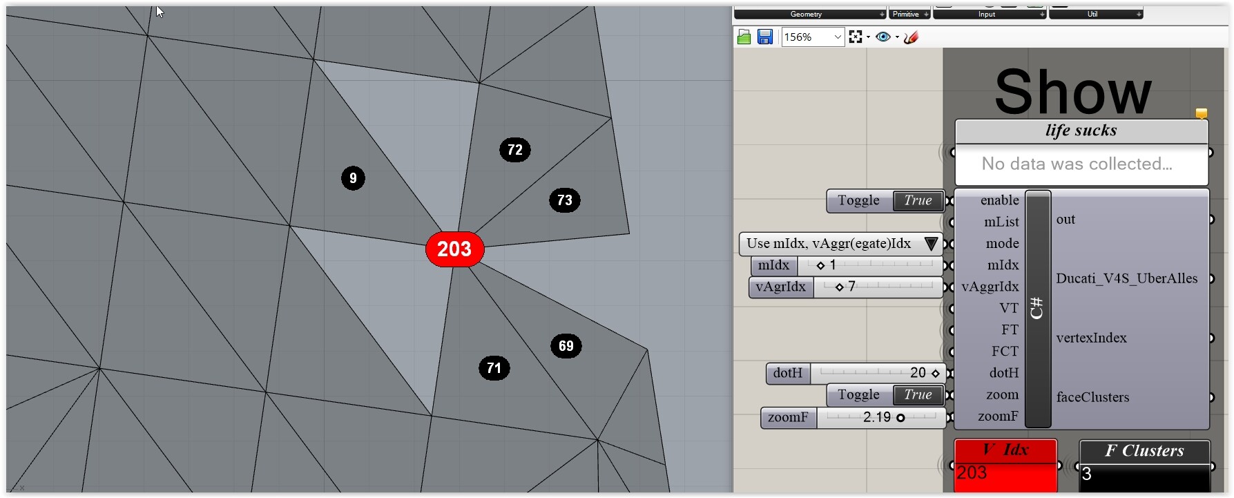
But … what approach to apply/use is not clear. See this isolated Vertex and the 3 Islands: Should you remove all involved faces … or just add some? (2 in this case). Meaning that this kind of “fix” is only - in real-life - possible/rational via an interactive approach on a per Vertex found basis (impossible without code: swapping volative <> persistent data per C# execution etc etc).