Layer Misalign with G-code 3D Printing

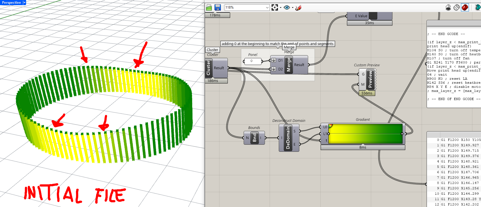
Hi, I am currently trying out non-planar printing with custom G-code on a Prusa Mk4. I am trying out the examples under Isocurves in Diego Cuevas’s book “Advanced 3D Printing with Grasshopper”. With reference this example, the layers start to misalign after reaching a certain height or towards the end of the print as shown in the images. Attached is our Grasshopper and Rhino file.

Reference Image (Cuevas and Pugliese 2020):

Failed Prints:

Files:
240425_Isocurves Non-Planar Test Print.3dm (154.3 KB)
240425_Isocurves Non-Planar Test Print.gh (81.0 KB)

For the first run using a 0.4mm nozzle with settings, a) Layer height – 0.4mm, b) Temperature - 200 degrees, c) Print Bed Temperature – 60 degrees, d) Fan Speed 30 – 40% and e) Feed Rate – 1200mm/m, we have the follow error in the print show here. The layers started misaligning around the 28th layer.


For the second run using the 0.4mm nozzle with settings a) Layer height – 0.3mm, b) Temperature - 200 degrees, c) Print Bed Temperature – 60 degrees, d) Fan Speed 30 – 40% and e) Feed Rate – 1200mm/m, we have the follow error in the print show here. The layers started misaligning around the 35th to 36th layer.


For the third run using the 0.4mm nozzle with settings a) Layer height – 0.2mm, b) Temperature - 200 degrees, c) Print Bed Temperature – 60 degrees, d) Fan Speed 30 – 40% and e) Feed Rate – 1200mm/m, we have the follow error in the print show here. The layers started misaligning around the 52nd layer.


Like to seek some help and advice on what is causing our prints to fail. I realised that the nozzle moves out of the original path, which is strange as the other layers print just fine and did not have the issue.

I also tried calibrating the machine - checking the belt tension, testing the X, Y and Z axis, there weren’t any issues detected. Any advice and help are much appreciated. Thank you.

2 Likes

Could it be something to do with the printer’s ability to move X, Y and Z, at a certain rate, all at once?

As you reduce the layer height, the layer shift happens at later layer numbers. Is the rate at which Z is changing relative to dX and dY causing a motion control issue?

Try running the same parameters again but this time slow the speed down and see if the print gets higher before failing.

Maybe :slight_smile:

3 Likes

:open_mouth: that’s awesome! you doing this with GH?! :open_mouth:

wait what :smiley:!

now I wanna see the Gcode blocks :smiley:

I was having similar issues during my first few weeks just using the regular slicer after I changed a bunch of settings.

basically, my printer nozzle started dragging real bad, cause the filament was coming out too fast relative to the printer speed.

after I slowed down the rate of the filament and speed up the printer and messed with a few other things, I was having success.

so mayb try “leaning” out the mixture of filament per feed rate of xyz :slightly_smiling_face:

I say go super fast xyz and go slower filament squirt action :joy:

obviously there’s some sort of sweet spot. the whole actual 3D-XYZ-axes-code is still very new to the printer industry – everyone else still doing 2.5D and calling it 3D lol.

when the curvature goes negative you might have a bridging problem at high speed. but the 3D contour might not have a problem idk…

To me it just looks like your ratio of filament volume might be kinda rich, relative to the speed of xyz travel…

eventually the richness builds up and the nozzel starts dragging and smooshing it over the sides…

Idk, that’s just based on my 2 cents.

I have a fdm 3D printer since 2018 and I have been moving the first steps in the clay 3D printing world about 1 year and a half ago using the very same book -which is an awesome source of info and inspiration-

I started looking into gcode and custom printing thanks to that very book, so my experience is 99% focused on printing clay -meaning, take my words with a pich of salt-

what I believe might be happening, is that while in clay printing you extrude a soft material over a printed layer which is still soft, with plastic fdm you are printing a soft material over an already-hardened wall

I’m trying to find a video I posted a few months ago about clay printing, where you can literally see the printed layers deform when the extruder passes by, due to the pressure of the clay being spit out, here it is:

so I think “at a certain height” the difference in layer height is becoming so meaningful that the extruded material does not find enough space to lie on, and goes out of path (while the extruder is still moving along the right path)

I see your E value is a function of the distance with previous layer, in such a way it extrudes less material where they are closer: I would play with those values


[edit] I’m editing this post as I have checked your code for generating the E values, and it’s actually flawless from a theoretical point of view :+1: (congrats on that)

but I have found the culprit, or at least I believe I have found it :slight_smile:

there’s a Move component here

that moves points along a mismatching tree of vectors, so it generates 47 new branches that should not exist:

I think you might have missed to put a Flip Matrix somewhere before this Amplitude component here:

the Amplitude Values data tree has been Flipped, while the Vector tree has not been flipped :+1:

by using that Flip Matrix (the Component was already there by the way :slight_smile: ready to be connected :slight_smile: ) the data structure problem to the Move component is solved

240425_Isocurves Non-Planar Test Print_inno.gh (89.1 KB)

this looks good:

how it was before:

that last crown of green dots looks like there’s a single layer with “wrong” E value… in reality it was 43 overlapping layers with also wrong E values: your machine was going crazy for a good reason :rofl:

note that your GH file had 3 definitions inside, I have examined and made that change just to the bottom one:

3 Likes

The first image would be easy to make using a subtractive machine like a standard 3-axis milling machine that started with a piece of standard metal pipe material. All it would take is a toolpath that mimicked the missing parts of the original pipe.

But a 3D printer is an additive machine, so from that perspective I thought the first image was pretty scary. If I were going to attempt to make that shape with my printer I’d work on varying the extruder feedrate rather than its XYZ position. I see no problem with (in theory anyway) calculating the volumetric feedrate in a way that tapers off to zero as the nozzle approaches the dip and then tapers up to normal as it exits the dip.

Doing this for each subesquent layer should result in a nice looking curvy edge. Once this was created you could even add a finishing top layer with full feedrate that outlined the final curvy top edge.

A few weeks ago I saw a posting that I can’t find right now from either PrusaSlicer or OrcaSlicer that showed how they were going to reduce layer seam marks by ramping extrusion rate up and down to taper the start/end point of each printeed layer so there was a gradual overlay rather than an abrupt start/end point.

1 Like

Seems before going for a such simple and cute non planner printing you should be a retired extrusion rate guru.

Hi guys, thank you all for your advice! I went back to my code to check and inno was right, I had forgotten to connect the ‘Flip Matrix’ component to the ‘Amplitude’ component. I went back to change my code and tested the printing at a slower feed rate as well, and it worked!

Thank you all so much for all your inputs and help, and thank you @inno for helping me detect the problem in the code and fixing it and checking my file! All of your help are very much appreciated!

1 Like