I would like to simulate an ackerman steering with IK. I have tried several times but allso failed severaltimes. I managed somehow to fix it with foreward kinematics but it is not really right.
I would like to make the following:
Point C can be moved from left to right but stays on the line it is now
Poit B and D follow the movement of pointC
Lines AB and ED follow B and D but are constricted to pivoting around A and E
Point A and D rotate with the lines AB and ED
The rectangles are attached to the line that goes to point A resp point E and pivot around these points
There is allso a blue and a black line. One is allways perpendicular to the left rectangle. The other to the right rectangle.
As i presume you have completely lost me now i will attach the 3dm file as far as i could get it.
Hope someone can help me out. ackerman steering.3dm (1.1 MB)
Rene,
Indeed a sample model tells more than a thousand words.
ackerman steering 001.3dm (1.1 MB)
The basic structure for this IK is one long chain starting off with a rotation ‘head’ and constrained by its ‘tail’. I used your circles ‘draaipunt’ for hinges because they are conveniently present.
Luc
Hi Luc
thanks a lot! I will investigate your model because i really want to be able to do this myself.
René
René,
By way of tutoring (and entertainment) I schematized the IK structure of the Ackerman steering.
ackerman steering 002.3dm (119.0 KB)
In fact the structure consists of 4 revolving points, presented in this model by circles (but they can have any shape you like). In most mechanical structure these revolving point are effectively physically present in the form of a spindle, an pin, an axle, a rod, a bold, a rivet etc…)
In each figure the 4 revolving points are lined up in one chain (A – B – C – D). The difference between each figure lies in the nature of each pivot.
Figure 1: Object A is used to ‘drive’ the IK chain. It is made rotating via keyframes. Objects B and C are IK joints Hinge (axis Z). At the end of the chain object D is the constraint, an indispensable element to complete an IK chain. The default constraint “Keep pivot location the same” allows the object to rotate (and even to scale) in order to meet the requirements of the constraint, so it actually functions simultaneously as a Hinge.
Is it imperative to ‘drive’ the chain by its starting object? No, it isn’t!
In figure 2 the chain starts off with a IK joint (Hinge) allowing the object to rotate relative to the World. Here object B is no longer a IK Hinge but the active ‘driving’ element made rotating by keyframes. Cute, isn’t it?
To make the set complete in figure 2 object C is made the ‘driver’.
Figure 4 shows the chain build-up of figure 1 but now translated to the ‘lines’ of the steering mechanism rather than the revolving points. The Bongo-pivots are positioned at the correct spots hence the system works just as fine. However beginners might consider it to be a problem there are only 3 lines and they would wish one could have 2 pivots on 1 object. However an absolute rule is : 1 object = 1 pivot. So to solve the issue an extra object is needed - in this case a point-object can do.
…
Then I wondered if an Ackerman steering was generally ‘driven’ by one of its pivots. It’s more likely the central rod is moved left/right (e.g. by means of a rack and pinion). A IK-puzzle 
A chain with 2 branches is the answer; as it were 2 chains sharing the same driver.

The Ackerman’s central rod however is not only moving left or right. It also balances and moves forwards and backwards. Bongo doesn’t permit an object to be moved via keyframes and be a telescope at the same time (even when the directions are unlike). The solution is to assign the ‘driving’ to an extra object (e.g. the rack) which drags along the Ackerman rod via a hinge-able and shifting joint (just like it would be in physical mechanical reality)

ackerman steering 003.3dm (115.9 KB)
Remarkable! As you can see in Figure 6, in an identical IK-structure the ‘driver’ can be made rotating instead of shifting.
Have fun,
Luc
PS Object E’ model 003 has no function in the IK structure. It’s merely present to illustrate the functioning of the system.
Hi Luc
Thanks again! I am trying to understand this IK chain and know now that it is not as easy as i thought it was. The situation is indeed that the system is driven by a central point on the line B-C. Not a rack and pinion system in my case. There are actually some more pivoting points in the whole setup but they where not needed to investigate the ackermann principle. My goal was to make an animation where you can move the points B and D inwards or outwards and to see what effect this has on the lines that are perpendicular to the wheels. Ideally they should cross each other on the line that is perpendicular to the wheel below the the two front wheels.
Ackermann says that the lines AB and ED should intersect at the heart of the solo wheel below. But sometimes this does not work as it should and you have to make the ackermann a bit “off” in the positive or the negative direction.
There is allso another steering system that i want to investigate. I will try to fix this myself on the basis of your tutorial but moght need some help.
I do nut understand what you mean by telescopic movement as there is no change in length of the lines AB, BD and DE.
Again, Thanks a lot
René,
If I understand correctly it is your intention to ‘investigate’ rather than ‘animate’ (create a video).
Making the distance between points B and D flexible isn’t evident. The stiffness of the rod is the basis of the Ackermann-steering. I guess you a seek a way to have the ‘length’ of the rod parametrical and observe the effect on the wheel-axes, isn’t it?
Bongo can be (mis)used to simulate parametric investigation by manipulating data in 1 single keyframe at tick 0.
An illustration of the effect of this parameter is in section 1 in this model: ackerman steering 100.3dm (115.8 KB)
The IK-chain functions like the one in the model “ackerman steering 001.3dm” (above) : a driver E, 2 consecutive Hinges D and B and a (pivoting) constraint A. To start with AB and DE are set orthogonal instead of slant. Then an extra point ‘regulator0’ is shifted between E and its child D. When now ‘regulator ’ is rotated by means of a keyframe (tick 10) point D wricks out the orthogonality. Using ‘regulator’ instead of point E itself is because point E will further be used to ‘drive’ the Ackerman-steering.
So point D swings out but of course B also shifts unfortunatly in the wrong way. To compensate the length of BD Expressions can be used.
In diagram 2 of the model you’ll find in the KeyframeEditoran for point B an Expression on Position X.

Now it’s getting a bit complicated.
The use of Expressions is described on http://bongo.rhino3d.com/page/expressions-in-bongo-2-0. Point B must the disabled ‘3D-tweening’ (see the Object’s Bongo Properties panel) in order to enable the use of Expressions for Position. The Expression -2*sin(#regulator0.RotateZ#*pi/180)*13.044 calculates the displacement of D caused by the rotation of ‘regulator’. 13.044 is the length of the line segment DE. Times pi/180 is needed because the trigonometric function uses radians instead of degrees. Times minus 2 is because the 2-fold of the displacement is needed to compensate. ‘Usage’ is set to “Added” hence point B is shifted in regard to its parent point D.
This system ('regulator and the Expression in point B) allows to steer the inclination of AB and DE by simply modifying the value in the keyframe at tick 10. Moreover the chain contains every element (driver, hinges, constraint) needed to simulate the Ackermann-mechanism.
In scheme 3 finally ‘regulator1’ only has just one more keyframe, at tick 0. The value in this keyframe remains constant throughout the animation and can is used as a “parameter” to determine the configuration of the Ackermann steering. Point E is made rotating via keyframes just like before.
Now you can position the timelineslider anywhere in the movement and examine the effect of lengthening of shrinking the Ackerman central rod by altering the value of ‘regulator1’ in the KeyframeEditor.

Is this kind of what you had in mind?
Luc
Good morning Luc
Yes, indeed. My purpose is to investigate. I design and build highend cargotrikes all customspecific and would like to investigate the effect of the distance the wheels are standing apart and the wheelbase on the ackerman principle. Therefore indeed the length of the ackermanrod is variable but that follows the angle of the steeringrods AB and ED . If you lengthen the lines they should cross where the rearwheel touches the ground. But as I mentioned before sometimes it is better to have a bit of a negative or positive Ackermann.
So actually I would like to be able to move the points B and D and see what the effect is on ackerman. I understand your version is a little different if I am right. The setup I actually use is a variation of the dualdrag link system you can find on page 18 of the recumbent trike design primer. I also send a picture of this steering setup.
What would be even more valuable to me is an animation of the Crossed dual drag link steering on page 19. Hereby you adjust the ackerman by changing the corner between the pitman arms. There is no explanation at all as how this angle should be determined. Not in the primer nor on the internet. I would like to change my steering system to the crossed dual draglink type but have to know what the angle of the pitmans arms should be if you change the width of the frontwheels and/or the wheelbase.
You can find my work at www.envancorven.nl.
Kind regards, René van Corven
Recumbent Trike Design Primer.pdf (1.5 MB)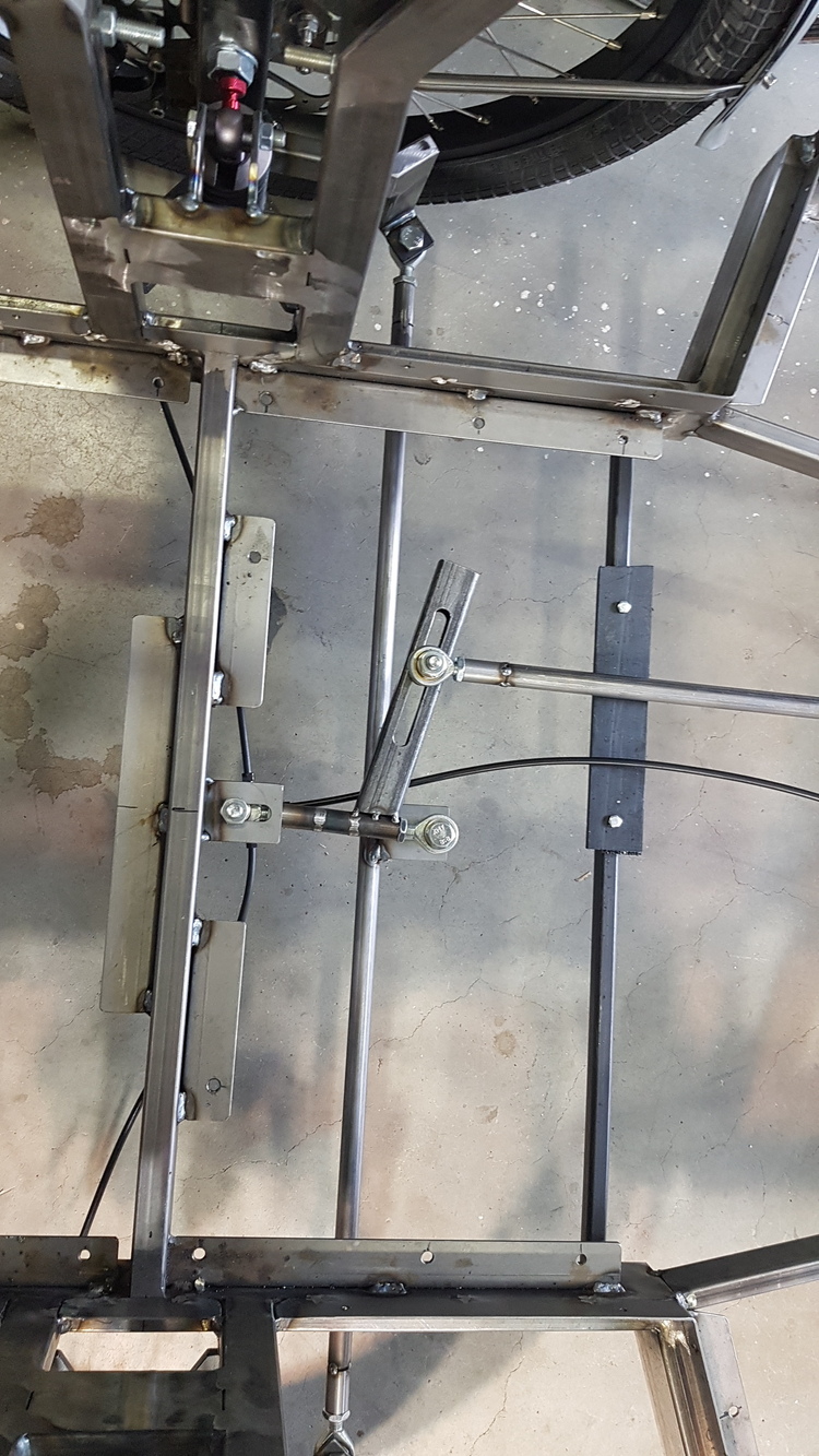
This conversation is continued in private.
I came across a Grasshopper model today that I had forgotten about - I wrote it. Described here with a link to download the GH file. Fully parameterized.
Ackermann Linkage for Catamaran Rudders
Using Rhino Grasshopper, from an SA forum discussion, August, 2021 (ProaSailor)

Ackermann_2021_Aug9a.gh (68.9 KB)