I am working on an umbrella-like pavilion geometry in Grasshopper. The main surface is generated from several curves that converge, and I am trying to soften the edge where these curves meet.
To create this soft transition, I attempted to connect the curves using a catenary curve as a fillet. While this works geometrically at first, the problem appears when I offset the resulting surface. Instead of getting a clean, uniform offset, the result behaves like a distorted extrusion, with irregular thickness and unexpected deformation.
This makes me think the issue is not the offset itself, but the type of curve used to generate the fillet.
My question is specifically: Which type of curve is appropriate for creating a fillet between non-coplanar curves so that surface offsets behave correctly?
For example:
Circular arcs
Blend curves (G¹ / G²)
Conic sections
Nurbs blend curves with curvature control
And more importantly:
Is there a recommended way to construct the fillet curve so that its normal direction remains stable and the resulting surface can be offset cleanly without collapsing into an extrusion-like artifact?
Any insight into curve construction strategies, curvature continuity, or surface generation methods that work well with offsets would be greatly appreciated.
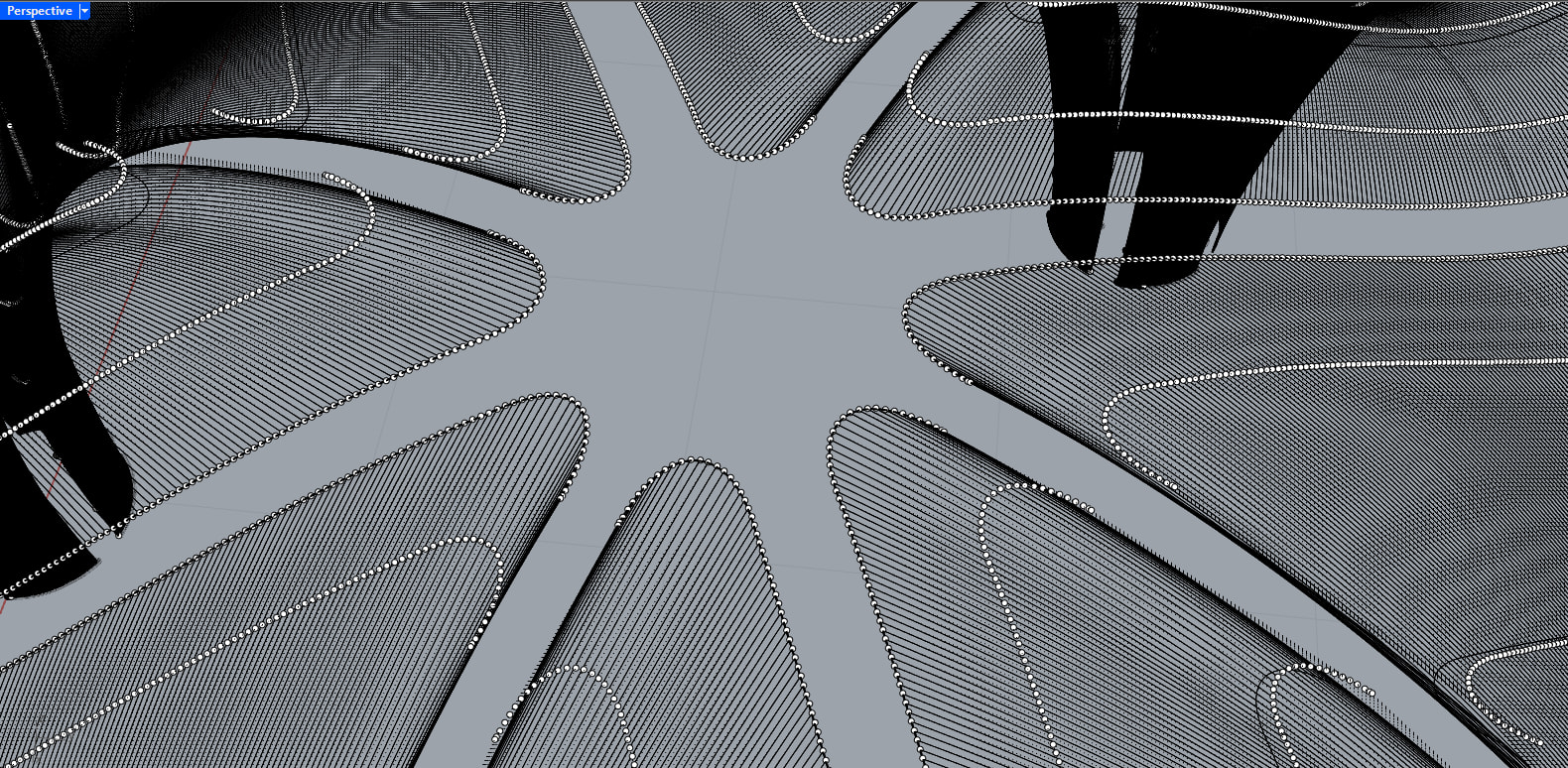
if you bake your original catenary-edged surfaces in Rhino, you’ll see control points flow like this, which is a bad situation for the offset and next eventual mods to be applied to your surfaces:
Wow, Inno, I can’t thank you enough for your time and effort. Thank you so much, I really appreciate it.
I was just trying to open your file on my computer and ran into a very strange issue. For some reason, the same Grasshopper script does not work on my end. I’m attaching a few screenshots here. If you happen to know what might be causing this, I would really appreciate your help.
I’d try lowering tolerance:
Rhino Options → Units → Abslute Tolerance set to a very low value, because your model is scales super small
after changing that option in Rhino you need to recompute GH solution (F5 or right click → Recompute)
Solved, Inno. I can’t thank you enough.
It was strange to me at first, and I honestly thought I was doing something wrong in Grasshopper, since I’m still learning. With your solution, I now have a much better foundation for understanding what might be happening.
Sorry to ask one more question. I just wanted to understand what absolute tolerance actually does. Does lowering the value mean that I can work with smaller geometry? I’m working in meters, and each cell is 3 by 3 meters, so even though the elements may seem small, the pavilion is actually about 217 sqm. I want to better understand how tolerance affects this type of geometry and what the best way to work with it is.
I’m attaching a screenshot showing a person with a height of 1.76 m for scale.
Once again, thank you so much for your time. God bless you.
absolute tolerance should define something like the minimum amount two values must be distant from each other in order to be considered different… which is pretty fundamental when dealing with geometries, expecially when relating different geometries
a given surface with given control points will be the same surface regardless of tolerance, same for a nurbs curve, but the intersection between them might change depending on the tolerance of the calculation (which is more or less what I think was going on in this case)
standard tolerance I think is 0.01 which might be good in some cases but not good enough in others…
working on architectural projects with meters as main units, a tolerance of 0.01 (1 cm) is fine -I guess- when you are massing buildings?
I do a lot of product design, my units are mostly millimeters, and a tolerance of 0.01 is usually fine for me (hundredth of mm)
Thank you so much for the explanation, Inno. That really helped clarify things, especially the part about how tolerance affects intersections rather than the geometry itself. Your explanation makes a lot of sense now in hindsight.
And thank you as well for the kind words about the project, but I have to clarify that it’s not mine hahaha. I really wish it were, but the project is already built. I’m just practicing by trying to recreate the geometry in Grasshopper. It’s actually an incredible project by Lake|Flato Architects.
Still, I really appreciate the compliment.
So, if I understood correctly, when working on architectural projects with meters as main units, an absolute tolerance of 0.01 m is generally fine for overall geometry and massing. But when moving into more detailed parts where elements or intersections are smaller than 0.01 m, it makes sense to reduce the absolute tolerance to something like 0.001 m to get more reliable results. Is that a fair way to think about it?
Thanks again for taking the time to explain this. I really appreciate your help.
…but the shape is not solved - I think.
the picture linked at ArchDaily show continuous surfaces. yours are not and the method does not help it - I think.
I think about that this way when deciding which project units I’m going to use: what’s the smallest dimension/feature I want to be able to safely and reliably measure? under that scale, I imagine things get “blurred”
for instance, if project unit is “meters”, what is the smallest distance I want to be able to reliably distinguish in my drawing?
→ if I want to be able to reliably measure up to the centimeters (1cm = 0.01 meters) then I would use project tolerance 0.001 (millimeters)
→ if I want to be able to reliably measure up to millimeters (1mm = 0.001 meters) then I would use project tolerance 0.0001 (tenth of millimeters)
That makes perfect sense, thank you for explaining it so clearly. Thinking in terms of the smallest feature I want to reliably distinguish really helped me understand how to set tolerance properly. I really appreciate you taking the time to share this, thanks again for your help.
Thank you for the comment, Jakob. I completely agree with you. I’m still very much in the process of learning Grasshopper, and this was simply the best way I found so far to approximate the geometry. I’m aware that the result is not fully resolved and that the surfaces are not continuous as in the project shown on ArchDaily.
I would really appreciate any suggestions or advice on better ways to approach this or improve the continuity of the surfaces. Thanks again for taking the time to share your thoughts.
i´d try SubD here.
loking closer at the images I find that none of the offsets is constant. the shells are thicker at the lower ends and the gaps wider.
model without gaps. trim later.