Hello everyone,
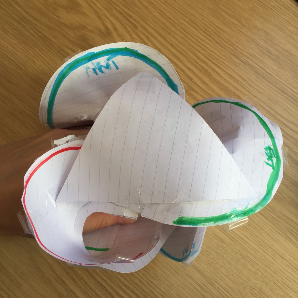
I am struggling with a borromean mobius surface. I made the curves in Rhino, here the file, and i’d like to make a surface which is a mobius surface and in the same time applying on borromean rings. If anyone have an idea about the procces it could be helpful,
thank you in advanceborromean mobius.3dm (97.7 KB)
That model on shapeways looks like it is just an offset of a single layer surface, so I’d recommend starting by modelling that, not trying to generate both layers from the start.
Focus on getting the topology right first, as we can smooth and relax the shape later.
Starting from the 3 interlinked rings, with 4 points evenly spaced on each, you can build the blue triangle, then using its centre point make the mesh quad as shown:
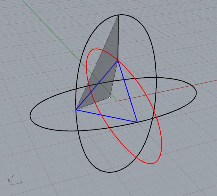
Repeating this quad by symmetry you can build the whole surface, then subdivide and smooth it to get the shape.
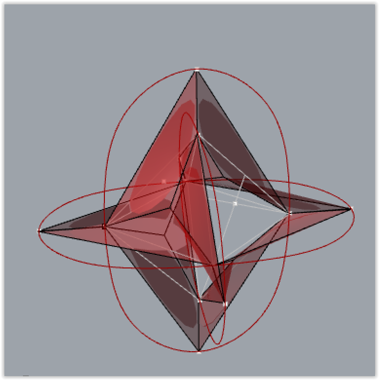
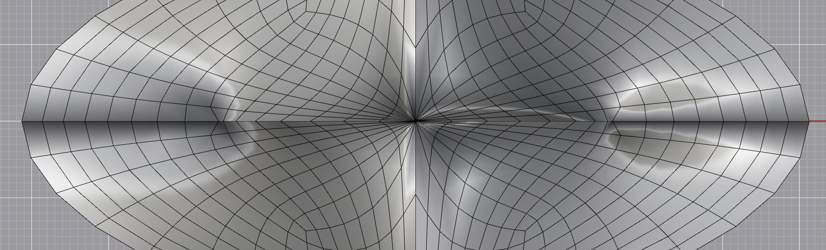
Here’s the result of applying Weaverbird’s Catmull-Clark subdivision on that mesh:

Note the discontinuity in the shading - because this is a non orientable surface, there is no way to consistently orient the normals. This wouldn’t be an issue once it is thickened into a solid though.
First join it into a single mesh, and run the AlignMeshVertices command to make sure all the vertices are properly combined.
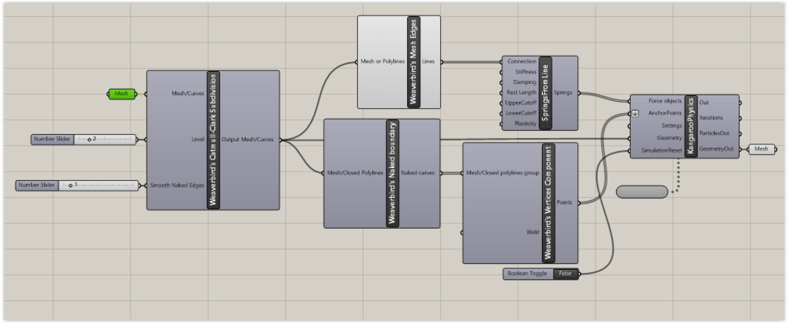
Then when plugging this mesh into the Weaverbird Catmull-Clark component, for the Smooth Naked Edges input (S), choose option 1 to allow the edges to become curved.
If you want to match the edge precisely to some predefined curve, you could also subdivide then relax it with Kangaroo while pulling the boundary vertices to the appropriate curves.

It looks like parts of your mesh are smoothing separately. Make sure you run the AlignMeshVertices command first with a high enough tolerance to combine any nearly coincident vertices. You might also need to run the Weld command (with a threshold of 180).
Regarding the boundaries in Kangaroo - first, I’d recommend doing this with the current version.
Here’s how it can be set up, using the OnCurve goal:
borromean.gh (12.7 KB)

Thank you very much for your answers. It helps me lots. Which pluging did you use in your GH file ?
Just Kangaroo - the latest version, which you can get from Food4Rhino
It’s working with the latest version.
Now I will adapt it to other kind of curves and double them. I will come back with a final definition later.
Thank you so much for your help 
Sorry for restarting such an old conversation! This thread has been super helpful, thank you so much to everyone who has contributed! Just one question, as can be seen in the photo below, there seems to be weird gaps coming up on either side of the shape. Any explanation and fix for this? Thank you!

If you have a non orientable surface, that means it isn’t possible to consistently orient the normals, so the break in shading is where it flips.
One possible solution can be to thicken the mesh into a solid, the boundary surface of which will be oriented.

Yes, for something non orientable, you’ll need to build the solid offset a bit more manually - offsetting to either side, then joining up at the edges.