All,
I am currently working with a model that was created by an architect which has in it several 3D polysurfaces that are curved (in two directions). For this example, we’ll assume that it’s a square cross section that has been extruded along the curve. My end goal is to create a centerline representation of these 3D items that I can import into a 3D finite element model for structural analysis purposes. I had done this before for simpler straight solid elements and had some decent luck getting it to work. As of now, I’m running into some roadblocks on my current approach.
Right now, my approach has been as follows. Any suggestions (or alternate easier methods) would be appreciated!
- Input the brep as a parameter
- Extract the edges of the polysurface
- Divide the edge curves of the polsurface along its length by a certain number of segments (using a slider so I can change this later).
- Extract the points from teh divided curve. This gives me 4 points at each “segment” along the 3D polysurface (making the square cross-section).
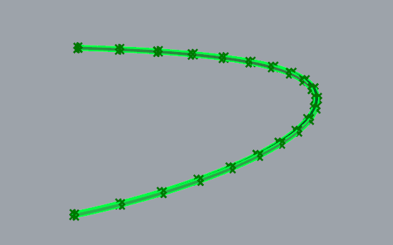
My idea was that for each bundle of 4 points I could find the centerpoint and then connect a curve (segmented) through the various centerpoints. This would then be my output to my analysis program.
The issue I’m having is trying to deal with the large list of values. I have a hard time 1) figuring out which order those points are organized in and 2) extracting a specific four points at a time from which I would want to evaluate a centerpoint for. I could easily extract ONLY four points, but I need to do this process on each bundle of four points. Again, I could probably split my list a bunch of times, but I would like to be able to generate a centerpoint for each segment based on the slider that I mentioned before. That is - if I want 10 segments, I need 10 centerpoints, if i want 20 segments, I need 20 centerpoints, etc.
Again, I’m pretty new at GH, so there is probably an easier way to deal with this. Let me know if you have any suggestions!