The shell is important because it is one of those (solid) operations that can hardly be performed manually, as opposed to other operations. Imagine having to dig a very articulated solid manually: almost impossible!
Unfortunately, currently, it fails many times and since its introduction (Rhino 5) small steps for improvement have been made.
With Rhino 8 the time has come to improve and correct all the indispensable tools that have made Rhino history, from blends, to offsets, to srf matches, etc.
The tools must be competitive and robust, not uncertain, otherwise we will end up, over time, with software full of commands and nothing more!
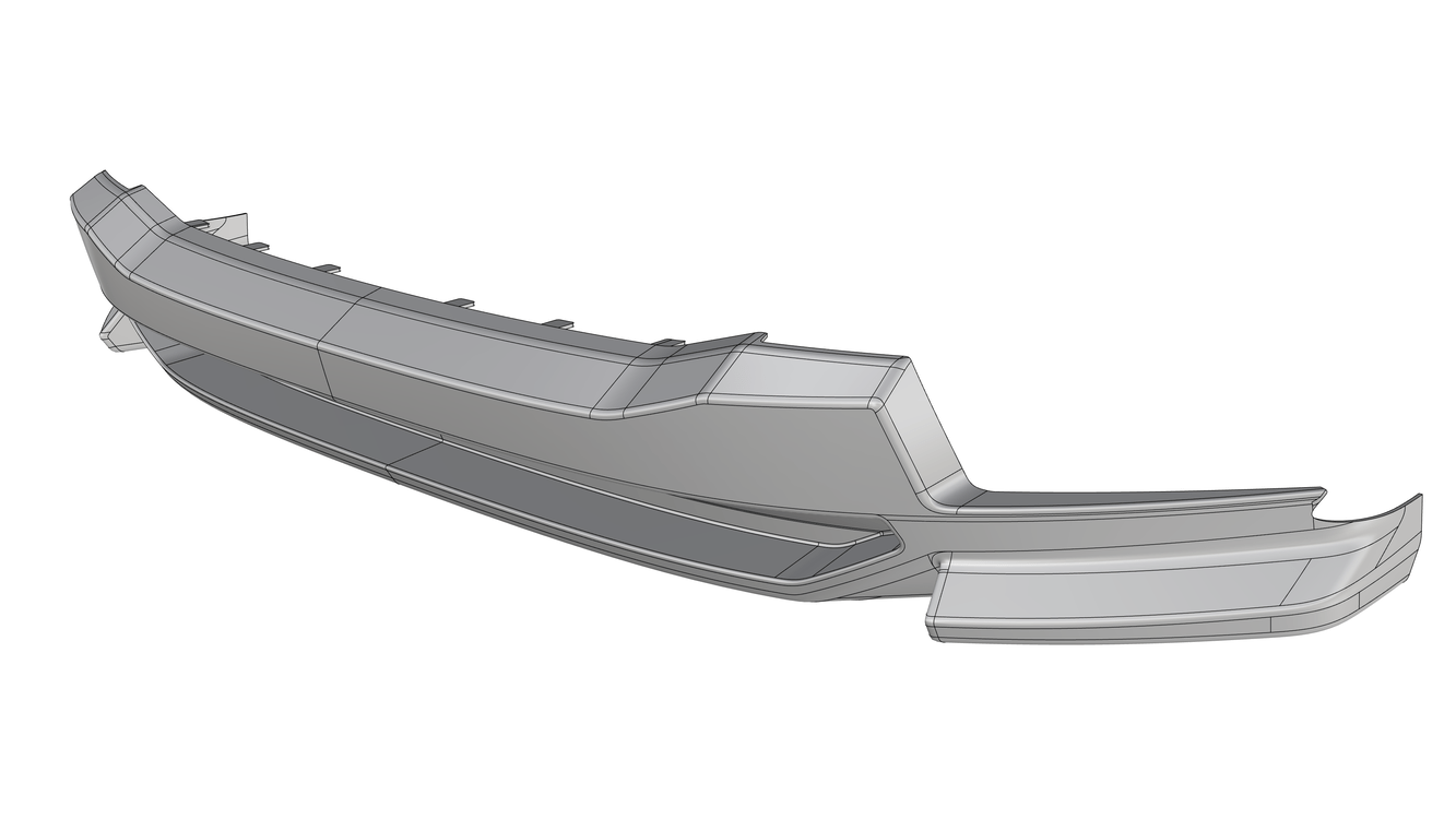
Recently, it took me roughly 4,5 hours to make a 3 mm offset surface for 3d printing of this front bumper, despite the good continuity between surfaces and angle tolerance of 0,1 degrees. The problem mostly comes from offsetting a polysurface consisting multiple joined surfaces. The offset joined surfaces get re-trimmed and shrinked, so this results into extremely tiny gaps here and there (like 0,0010854 mm, for example). This forces me to untrim the offset surface, extend its border, then trim it again with manually built trimming curves (mostly extracted edges of the nearby surfaces or blend curves). If the offset surfaces were NOT shrinked and behaved in the same way as offsetting a single surface (preserving the size of the original, no matter whether it’s trimmed or not), that would help with having less errors like that.
There were also a few self-intersections on the offset surface, so I had to untrim and trim again those areas and build blend surfaces there.
4,5 hours is super slow for such a basic task. I know that “Offset” is not exactly “Shell”, they are different commands, but they are supposed to work in the same principle, i.e. offsetting the surfaces to build thickness.
Making that tool which @theoutside has written about above could be also the solution for that purpose (IMHO). Because if you would close your bumper temporarily on the back to have closed shell (some ugly shapes on the back only to close it up) and you would use voxel (isosurface) with offset 3mm and quad remesh later then you should get the inner shell with proper offset. After that you should only change it NURBS. As output, you would have the outer closed shell of the bumper and the inner shell which would be offset 3mm from the bigger one. After that, it would be needed only to boolean subtraction of that couple and trim it on the boudaries of the bumper - in places where that bumper will end on its surface. I`ve done some acrobatic solution like this a few times on similar cases as yours.
It has 2 cons:
voxelization, remesh and offset is slow as hell in GH so to get decent quality it should be multithreaded and done without GH. It`s because you should get about at least 2-5 mln polys on the case as yours to have a smooth shape with details (to have a nice smooth surface inside with preventing details from being loss).
a whole process is time-consuming when it`s needed to do it manually without magic button
It has 1 biggest pros:
it`s bulletproof even on complex shapes.
So if that voxelization with remesh and offset won’t handle few mln polys as output with clean small details on the 2m bumper then it will be useless in your case (quad remesh won`t be smooth and details will be lost). So I will keep my fingers crossed that we will see a proper solution for this during the 8 cycle. I hope also for some improvements in thickening / shell / offset in examples as you said.
That looks like it would be a great piece for the developers to use in their refinement process. It looks generic enough that if you don’t say who your customer is it shouldn’t be an IP problem to send it to McNeel. Or maybe you could take the original underlying surface and modify or distort it so it doesn’t match your customer’s (employer’s?) part but still demonstrates all the offsetting issues?
It’s a model for a customer, so I can’t share it. However, I may create some smaller example with similar surface transitions if “McNeel” needs it to test their improvements of the “Shell” and “Offset” commands. But the main problem, as I mentioned in my post above, is that Rhino shrinks the offset surfaces, so this creates a real possibility for the latter to have some tiny gaps between the joined edges.
It also comes from the fact that angle tolerance is very important for offsetting. For example, if the input geometry has 1 degree deviation of the tangent continuity between two surfaces, an eventual offset of 3 mm may result into two separated surfaces, because 1 degree crease, when projected to normal at this distance, makes about 0,0523592 mm gap OR 0,0523592 mm self-intersection (depending on whether the 1 degree difference in tangency between the input surfaces is towards the outside or inside of the thickness). With an absolute tolerance of 0,001 mm that would immediately translate into a gap that needs extra manual work to be fixed.
However, an angle tolerance of 0,1 degree (I use this to minimize the unwanted gaps when adding thickness to parts) has a better chance to make the offsetting as expected, because 0,1 angle and 3 mm offset in the normal direction results into a 0,0052360 mm gap. I use 0,001 mm absolute tolerance, so even such small gaps could be problem sometimes. For parts that need thickness I put some extra time to make sure that the tangency between their surface edges are as close as possible to 0 degrees, because that’s vital for having a good offset wall.
Sometimes I just prefer to not join my primary surfaces and make their offset version with the “Loose” option to make sure they will be translated with the least possible errors, then I add all the fillets manually, but it’s usually slower that way. The benefit is having cleaner surface quality and smaller file size. But as I said, time is a constraint.
What about pushing that geometry to ACIS kernel (Design Spark Mechanical or ViaCad) only to do offsets /shell there? Maybe other affordable CAD engines will do those offsets better (before Rhino team will fix that )?
I have some stupid question. How do you know what fillet value you should give on inner side to have exact 3mm? Have you checking “r” value on every fillet of outer surface and do calulations manualy? Because if you will give bad fillet value on the inner side then you will have less or more than 3mm thick. It`s a lot of work.
another workaround is to mesh the part, then offset the mesh, then clean up any bowties, then quad remesh, then tosubd, then tonurbs.
then take that object and connect it to the original surfaces, or boolean the result out of the a solid object to create a shell. Not an ideal workflow, but it does work and I’ve done it to save me in a pinch.
also remember if all you need to do is make wall thickness for a print… mesh it then offset the mesh with the solid option… that will get you to a print with very little issue. as most printers will ignore internal overlaps when they make the slicing set up.
The best way is to keep everything within Rhino, because other CAD programs actually may destroy the original surfaces. For example, when importing Rhino models or STEP models into SolidWorks to add some fillets, the latter tends to split cylinders into two halves. Then this model is far worse when it’s imported back into Rhino. The same happens also on spheres and even some free-form degree 3 surfaces that are a single piece in Rhino but SolidWorks “wants” them to be separated into two or more pieces. Solidworks actually uses fake geometry and increases the file tolerance to some huge numbers in many instances, in order to make the models work somehow and to visually fill gaps between surfaces (kind of a forced “! _JoinEdge” that Rhino also has). However, this fake approach leads to real gaps and self-intersections outside of SolidWorks, when its models are exported as IGEs or STEP, for example, and imported into Rhino. It’s a really annoying issue, this is why I avoid using anything which is not Rhino a much as possible.
another thing to consider about shell… if you do it early, before you have fillets or complicated blends applied, you can take those offsets of your original base surfaces and bank them for later development… this will save you time later. Again, not ideal, and we all agree this needs to be improved…I’m just trying to share tricks I’ve used in the past to workaround the current limitations.
I usually work with exact numbers of the fillets (like 3 mm, 5 mm, 20 mm, 100 mm etc), so it’s fairly easy to calculate the necessary radius when doing a thick part. I only need to add or remove the offset thickness from the original radius value. However, this may lead to human errors, because if I accidentally add 3 mm instead or removing 3 mm from the fillet radius, that would obviously make the things ugly.
Another issue is that I rarely use radius fillet. Instead, I work mainly with G2 curvature “! _BlendSrf” and “! _VariableBlendSrf”, so basically it’s impossible to make a perfect 3 mm offset of a blend surface manually. But usually deviations in offset of less than 0,1 mm are not a big deal, as long as the part is fully enclosed.
Shell or offset thick models are also used in manufacturing for moulds where NURBS geometry is needed, this is why mesh models are not a solution. Vacuum forming industry is another filed where NURBS geometry of the thick parts is essential. Also, some 3d printers work better with NURBS geometry than STL mesh models.
“Quad remesh” fails quite often to deliver a good quality mesh from a NURBS model. I tried that multiple times on different models. Also, converting it into SubD and then into NURBS results into big deviation that’s not acceptable for manufacturing. While 0,1 mm deviation could be fine for making CNC-milled moulds, anything above 0,5-1 mm deviation is way too much. Doing offset surfaces with NURBS is still the most accurate way, just takes time to clean up the errors with lots of manual work.
My example above (animated gifs) was subd shape which was converted automatically into NURBS. So I have no base surfaces there. If I would have a base surface I would do as you said. I haven’t said that thickening is impossible in Rhino. I only make my wish to maybe in 8 cycle give it a little love cause it’s very helpful in many industries. In 3d printing fast hollowing is saving money. I you would want to do a polygon version of hollowing please look on MeshMixer because it has the best hollowing in polygons and it`s worth to look how fast it works. I would love to see similar solution in Rhino. In the second hand I would like also to see some improvement in offseting/shell in pure NURBS style cause as everybody knows Rhino is one of the best surfacing software in the World
Other CAD programs have an automatic analysis tool to show the radius of fillets. In Rhino, you can extract a cross-section isocurve and use it to evaluate the radius:
! _ExtractIsoCurve _Pause _Toggle (you have to toggle the direction, because by default Rhino always tries to extract isocurves on fillets and cylinders in the wrong direction first, not sure why).


 )?
)?
