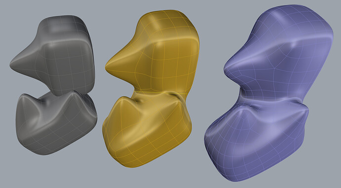
Will Sub-D provide new and better ways to fillet?

Yes it means just that, you can look for YouTube videos for Retopo and you will see that Blender, Modo, Maya, Topogun, 3Dcoat, Zbrush all do it, fairly well, for organic things like characters, nature pieces, etc. I think Rhino could have a leg up in this space eventually fo rethink type of work you do.

The LIDAR in the next iPhone, if similar to the current iPad Pro is fantastic for getting depth information for AR placement of objects, or like they showed yesterday for the new iPhone Pro: detect foreground from background elements for focus on a camera, etc. So it’s basically a camera helper, and sure, you can get the rough dimensions of a room or a window (in those cases AI helps them assume straight lines to complete the missing information). But for the work we do? I don’t think it will be very useful. Your manual ruler/T-square/calipers would to a much better job. Maybe it could be good for a very organic form of a very large casting or something like that.

Just look at the resolution of the iPad’s LIDAR here (dots caught with infrared camera):

Here’s a scan of a show with the iPad Pro’s LIDAR:

Thai is the shoe it was trying to scan:

The only possibility where I can see this scanner being useful is if Apple includes the depth information of photos in their AppleRaw photo format. And they with a bunch of those a photogrammetry program could potentially do a much better job than just using flat images. Yet, IF Apple includes that info, someone has to code that into a good app. A lot of IFs for a $9.99 app with limited market appeal IMO.

Best,

G

1 Like

There’s a reason why state of the art scanners like the Artec Leo cost what they cost.

A screenshot of a scan with the new HD mode:

3 Likes

Pity that didn’t work out. Maybe as @martinsiegrist indicated, just too good to be true.

Maybe when/if Rhino does implement this, there will be a way to add a blend shape deformer for fillet-like rounded edges and internal corners. Perhaps a Rhino 8 feature?

Hi Daniel,

Trying your SubD Fuse gem here. I think I already broke it? Or maybe I’m missing the logic of this?

Subd_fuse01_errors_gf_201015.gh (10.5 KB) subDfuse_test01_errors_gf_201015.3dm (1.7 MB)

Related to SubD workflow, I just had to do some very simple things here to get to this, and the friction in Rhino SubD continues. (cc @theoutside)

  1. I wasn’t sure if I needed to Subdivide more the primitives to get them to work, so I went ahead I subdivided them. And I just realize that there is no unsubdivide workflow/tools in Rhino? that’s pretty destructive IMO.

  2. Slide does not let you slide a copy, only using gumball (with Ctrl, but of course Gumball cannot easily (if at all?) be aligned to the slide direction.

  3. Add loop only allows you to add one loop. This should have a number to at least add an even spacing set of loops. Not one at a time, that’s too much work and too unprecise.

Thx,

G

1 Like

Hi @gustojunk,
Thanks for testing.
You are using it exactly as intended, and your file works without changes on my current build:


I think what you are seeing is caused by a bug which resulted in some flipped normals in the output of the first Fuse, which then cause problems when it is passed to the next one.
I caught this just a bit too late to make it into this last Beta release, but the fix will be in the next one.
If you want to try a hotfix, it should work to just put this file in place of the existing one in your Rhino WIP\Plug-ins\Grasshopper\Components directory:
Kangaroo2Component.gha (314 KB)

This shape is a good example of the kind of thing the tool should work well for - reasonably dense mesh, similar quad density on the parts where they meet, and simple intersections.
To manage people’s expectations though - Fuse will not work in many cases where the intersection is more complex (i.e. each fusion seam doesn’t form a single loop). Also large faces on one of the shapes that pass through multiple non-contiguous faces on the other will probably break it.
These things will likely be possible to improve somewhat, but this approach might not be possible to make ultra-robust for really complex booleans.

Also - the input is not required to be closed, though open shapes might behave less predictably, and the boundaries should not cross the parts where the 2 pieces join.

Thanks Daniel, I’ll update that bit and bang on it some more. I’m seeing when it works and where it fails, but I can’t make sense of it too.

It would be good to see a faceted mode to the results too so we can learn better on its successes and failures. Especially to see what changes when I change that accuracy slider.

You’ve seen that I needed to SubDivide the modules for this to work (and then bitched to Kyle that I broke my toys after banging them hard), which makes sense, but makes things less editable. Adding an input subdivision value at the GH fusion component level would be nice.

G

With the build in the post above, it does still work even after I unsubdivide* your input by one level.
Subd_fuse01_errors_gf_201015_unsubd.gh (32 KB)


I like the idea though of adding an option on the component for a subdivision value.

Thanks Daniel,

I played with this some more. I still do not fully understand the logic of what merges, where. I do see that some of my input faces are omitted, and some new connecting edges (and faces? ) get added.

I tried to push this to the limit a bit more (because you know, otherwise you would get bored). Tried to get something closer to Ian’s machine posted above:

Seeing only the smooth result in very cryptic. I think you really need to have a faceted preview mode here.

Also even if I bake and look in faceted mode, it’s still cryptic:

By adding some Object display more and color change I can see a bit more to start making sense of your logic, but still kind fo cryptic:

I think it would be great to see a thicker border of the new boundary being used on each boolean operand, and a different color for the strips that get added. Then when we move things around in real time we can see exactly the fusing in action.

for example, I still do not know how to get this of this weird lip in the front…

file here with meshes internalized:
Subd_fuse03_errors_gf_201015.gh (24.9 KB)

G

PS: Bigger picture thoughts…

Besides this great fusing potential, I know it’s not ‘your department’ but it’s so shocking to me how slow and cumbersome is editing just 5 simple prismatic, and mostly orthogonal meshes/subDs like these ones in Rhino. I should be able to fly through this, and I can’t. And I’m using all the tools you guys have, so this problem is not a user error.

Examples: Deleting edges sometimes deletes nothing, or leaves crap (loose verts) behind, gumball keeps getting on the way of Shift-selecting, cutting (Ctrl-X) poly faces does nothing (cutting half a sphere and pasting it back is the fastest way to split it!), swapping selection filters is obscure, what I have selected is obscure (no heads-up display telling me how many what I have selected, it’s useless to know “1 mesh edge added to selection” I need to know how many edges I have selected!), edges keep getting unwelded, no command to circularize a loop, growing (expanding) selections is not possible, locking some vertices (or any subobject) is not possible, I cannot add loops in two different places at once… it’s all so painful, it reminds me of SubD modeling in 3DSMax circa 2000, before logical and intuitive things like Silo, then Modo came to the market and showed there was a 20x better way.

Maybe V 7.x or V8 would be good for users with higher expectations, because this is just plain painful right now.

ugh…

Gustavo, I don’t know if this helps with the experimentation, but here’s an upload of the 3dm nurbs model I made of that exhaust manifold, which I had screenshotted above.

I’ve uploaded it because, on reading (or really just skimming, I won’t pretend to understand it) this paper (Nuvoli et al 2019) –

that @DanielPiker mentioned in this earlier thread …

… I can see that once converted into quadrilateral meshes (if I’ve got the idea right), it should be possible to union the basic shapes in the model via Fuse and have all the intersections ‘melted’. If that were so, that would be kind of mindblowing. I think that’s what you’re getting at Gustavo?

So possibly this 3dm could be useful to play with. There are two model layers: the constituent nurbs ‘primitives’, and the nurbs union of them.

Frisco exhaust manifold.3dm (6.9 MB)

Just for fun, here’s another view of the prototype, which gives an indication of what a fuse operation might try to approximate.

I’ll ask a question of @DanielPiker too. I had wondered if Kangaroo particle physics might also be a way to approach these sorts of models – is an erosion and deposition process possible, where sharp external corners are ‘eroded’ smooth and internal corners are ‘by deposition’, filled smooth? That would give a similar effect. I completely understand if that is a fanciful idea.

Superseding my post immediately above.

I found this video that demonstrates Modo’s Mesh Fusion tools:

which indeed is mindblowing, and seems to be absolutely ideal for what I do. The question I have now, is whether @DanielPiker’s Fuse can do this.

“Strip Width” and the other strip properties virtually do what ‘fillet radius’ would do, plus the surface properties of the “fillet”.

1 Like

Hi Ian,

I tried it, breaking up the problem a bit, and excluding all drilled holes. I also had to extend the parts intersecting the upper flanges, otherwise they would no boolean union.

I think this has potential if the QuadRemesher gave cleaner results:

This is the problem with the Quadremesher. I cannot get it to make clean surfaces that are not bumpy.

Anyone has any advice for this? (I tried several settings, guide curves on, off, hard edges on/off, no luck )

Rhino file here and GH with the data internalized.Uploading: Frisco _fuse01_bumpy_gf_201016.3dm… subd_fused_frisco01_internalized_gf_201016.gh (287.2 KB)

2 Likes

Wow, @gustojunk, so close! Here we are, right on the edge of Rhino 7 retail release, and there’s this breakthrough feature here. Some QuadRemesh debugging (@Trav?) , and some more work on @DanielPiker’s Fuse plugin at UI and guts levels and it’s there, right up with Modo’s Mesh Fusion – a hugely marketable feature.

Will it scrape in at five minutes to midnight for the release, make it in a v7 update, or is it doomed to be a v8 wishlist item? I really want to know. Would Kyle @theoutside or @scottd be able to shed some light on this?

Thanks @gustojunk.
The tool definitely does still have plenty of bugs and strange behaviour for many cases, but this doesn’t seem like one to me - in what you show here it looks to me to be working just as it should. What other result you’d expect for this? - your input is on the left, result on the right.

Now as a human I can guess that maybe you’re after is to change this region:
image
into this:


…and manually I can remove those faces and fill in with a new strip of quads.
I don’t see how the algorithm could know that this is what you want though, since those extra faces around the lip do exist in the input, and in other cases might represent details you want to keep.

I do agree that it would be nice to have better tools to make this sort of process easier, though I would see it as clean-up after Fuse rather than part of Fuse itself.
I was actually looking at something recently in relation to this thread, that could maybe be relevant for this sort of hole filling with patches of quads:
(input in grey, filled result in orange)

As for showing more clearly the borders/new faces in different line weights/colours - good idea. I’ve been using something like this for my own internal testing and development of the tool, but can see how revealing more of the workings would probably make it easier for users to understand and control too. (btw - re faceted mode, in Grasshopper just connecting a ‘Mesh’ parameter component to a SubD output gives you the control polygon). For the Rhino command there’s still other stuff to figure out about how best to show both input and result in a clear way, but agreed that faceted mode should be an option.

3 Likes

Hi @Ian

That Modo video is interesting - I don’t remember seeing this feature before.

The approach and result there is quite different from what I’m doing though. It looks like they do the actual joining on a much denser triangulated mesh, but keep a parametric relationship with the input solids, and show their coarse SubD wires in the preview.
I think something like this would be possible to put together in Grasshopper - performing the boolean on the densified mesh with each update, then finding a strip region around the join and smoothing it.
It’s a fundamentally parametric approach though, and once you wanted to bake or do any further processing with the result, such as converting to NURBS, it looks like you’d be stuck with that mesh with thousands of faces, since the objects never actually get joined at the coarse quad level with their approach. This may be a problem or not, depending what you want to do with it.

@DanielPiker this is super interesting!

I fused two SubD’s, created a section curve through the transition and ran a QuadRemesh with the section as a guide curve for a loop…

Because I don’t like triangles…

Nice - I wonder how this compares with just doing the boolean on either the control polygon meshes, or the SubDs converted to NURBS, then QuadRemeshing that.
Sometimes I think it is useful to be able to preserve the exact SubD quad layout of the objects away from the join though, and with QuadRemesh you always have to remesh the whole thing.
Sadly it turns out it is topologically impossible to have the best of both in the general case - if you strictly preserve the quad layout away from the join, you usually need at least a few triangles in the connection.

I grabbed a couple of quotes from the Modo literature that points to what you are saying –

I think I like your current approach better, because the quad mesh can go back to SubD or nurbs, from what I’ve read here for Rhino7 –

The parametric aspect of Modo’s MeshFusion is appealing, but by far the strongest appeal of Modo’s MeshFusion to me, are the Strip Properties to manipulate the strip region around the join. Could that be done within your quad mesh fusion approach? I do note though that maybe you have already indicated how Fuse might approximate this:

hi Daniel, yes what you show filled manually is what a human would want, and I wasn’t sure how to place the flow of my polygons to achieve that without manual intervention. Leaving holes like you show in your video and let the tool ‘fill them’ would be a good approach.

Another issue I see is that if we try to fuse various objects that each has been Quadremeshed individually without regards to each other’s poly flow and count it makes this really hard.

I’ve been testing QuadRemesh extensively and I still do not see how I can make it useful for product design work, it’s soooo close, yet still not there.

Here’s an example of this ‘so close, yet not there’ (cc. @Trav):

GH file here (internalized):
frisco_main_form_bad_quadremesh_gf_201016.gh (104.0 KB)

G

1 Like

I notice that the input type of the current QuadRemesh Grasshopper component is Mesh
So if you are connecting a Brep, this means it is getting automatically meshed by Grasshopper using default mesh settings before it ever reaches the QuadRemesh code. Meshing it yourself with custom settings gives a bit more control.

I believe this also means that the ‘Seam-Edges’ setting is having no effect, since it doesn’t ever have any Brep-face boundary edges to retain. Only the ‘Hard Edges’ setting currently matters.

I’m guessing this is just an oversight in how the Grasshopper parameter inputs are currently set up, since Brep input and edge preservation does work in the Rhino command.

Yeah I had no idea about that. This seems very broken IMO. Could it be fixed? If I select a Brep as input, I really mean I want that Brep as my input, not a default mesh representation of such Brep.

That still does not explain why tow of those 3 towers look sharp and the other one doesn’t.

G