According to Rhino 6, it’s even less than G1. You should be able to notice that deviation with the “Light lines” analysis of VSR which is an incredible tool that I miss so much in Rhino
.
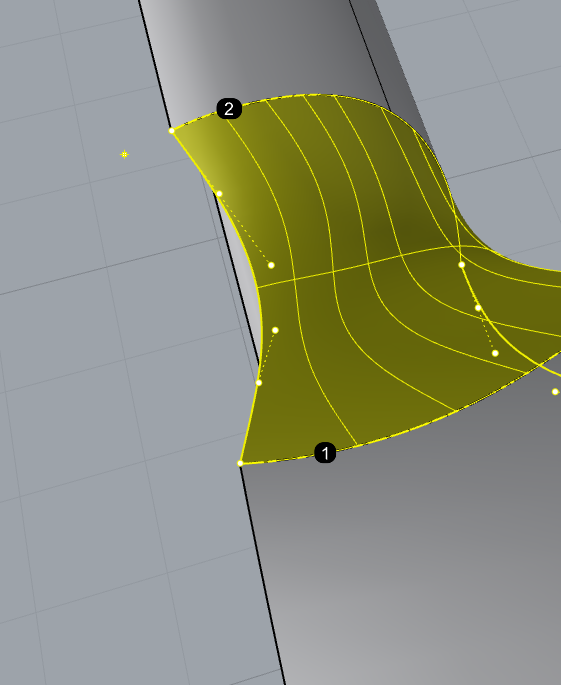
If you extract that upper surface and use Rhino’s “Match surface” tool (either with 1 or 0,1 degree) with G1, you will notice that it will slightly improve the tangency. If you use G2, it will make it perfectly smooth, however, that will move some points of the 3rd row in a bad way*. This is why, in order to preserve the flow, I used “Match surface” with G1 and then adjusted the 3rd row of control points with the “Move UVN” tool. Of course, I use purely visual feedback to adjust these, to I can’t achieve a true mathematical G2. It’s more like G1,95
Visual smoothness is more important than what a mathematical G2 is. As I said earlier, in some situations G1 or G1,5 or G1,9 is better than G2.
Also, it’s important to notice that Rhino 6’s “Match surface” with G1 and 1 degree deviation improves what VSR considers to be G1 and G2. You can check that with both, Zebra analysis and Curvature analysis (try all 4 options there with the minimum and maximum setting).
I posted an example of what an Alias modeler did with deviation analysis and it was lacking proper flow of the control points. That’s because surface continuity must be checked with Zebra or Light lines, as well. Curvature analysis is also a powerful tool for finding tiny deviations.
I played with the mesh settings of the analysis mesh and that read area disappeared. However, the deviation is still noticeable. It tells me the continuity could be improved, because the Zebra analysis also shows zebra stripes that don’t meet were the surface edges meet.
Don’t get me wrong, I don’t want to argue. I just wonder why VSR considers this to be nearly perfect curvature while in reality it’s less than G1. Even Rhino’s “Match surface” with G1 and 1 degree deviation improves it to the point that the zebra stripes get nearly perfect, which tells me that the angle achieved with VSR is visually greater than 1 degree. With “Match surface” G1 and 0,1 degrees the zebra stripes get even better. And then, adjusting the 3rd row of control points with “Move UVN” make it finally perfect.
Right, but this convo is kinda pointless because there’s no real way to quantify an end point, since all you’re doing is staring at Curvature Analysis, which as you might gather I think is a totally dumb way to talk about continuity. You’re going over a model that I never said was class-A, and holding it up to Class-A standards. “could be improved” could apply to every single trimmed edge edge on every model in the known galaxy. G0 is a tolerance, right? G1 is also a tolerance, right? G2 is a tolerance, right? I told you up above - that edge has a max G1 tangency break of 0.17 degrees, according to VSR. Here’s that graphic again:
So - could that be improved? Sure. Does it need to be? That depends on what the target is for G1. Most people who try to build to G1 can’t hit 1 degree. For me, personally, I consider G1 to be anything under 0.2 degrees tangency break, which that edge is. If you had said to me “can you make this edge less than 0.1 degree” I would have said yes, of course. But it’s as if we are having a conversation where I set my file tolerance to 0.001 and you come along and point out that my file tolerance could be tighter. Okay, sure, but…? So when you say:
That’s a statement made without any context, and it’s being judged using a seriously flawed method. I’m showing you what numerically those edges are matched at - it’s all in the screenshot of the table - you can decide that you think my standards for G1 or G2 should be higher, but the way you’re assigning numerical values for your surfaces (G1,95…G1,5) is being pulled straight from your posterior. You’re just making up numbers, with the only basis for them being a curvature analysis color map. Right? I mean, tell me how you’re coming up with things like G1,5?
The funny thing is we probably agree on most of this. I know that Rhino’s MatchSrf will do terrible things to the third row of points because that happened to me too! So I massaged it manually using Control Point Modeling to get it where I wanted. Within my tolerances. The one thing we don’t agree on is that Curvature Analysis is a useful in quantifying edge matching. I mean - look at the updated pictures you posted - what the heck is that red area along the edge of the original surface? Seems to me like that needs fixing. Aren’t you going to fix those red specs? Couldn’t that surface be better?
As I mentioned in a previous post, using a regular “Match surface” with G1 will help to achieve a better tangency. And that takes just a few seconds. I think it’s worth it. In Rhino 5 it could do it the same way as in Rhino 6.
I know that everyone has own preferred methods to analyze continuity, but I would never underestimate the usefulness of the Zebra analysis and Curvature analysis. They have proven to be very reliable for my modeling during the years.
It’s pity that I can’t save and send you the improved surface so that you can check in with “Light lines” in VSR. By the way, have you tried to see if “Light lines” will return proper transition of the coloured stripes where the surface edges meet together?
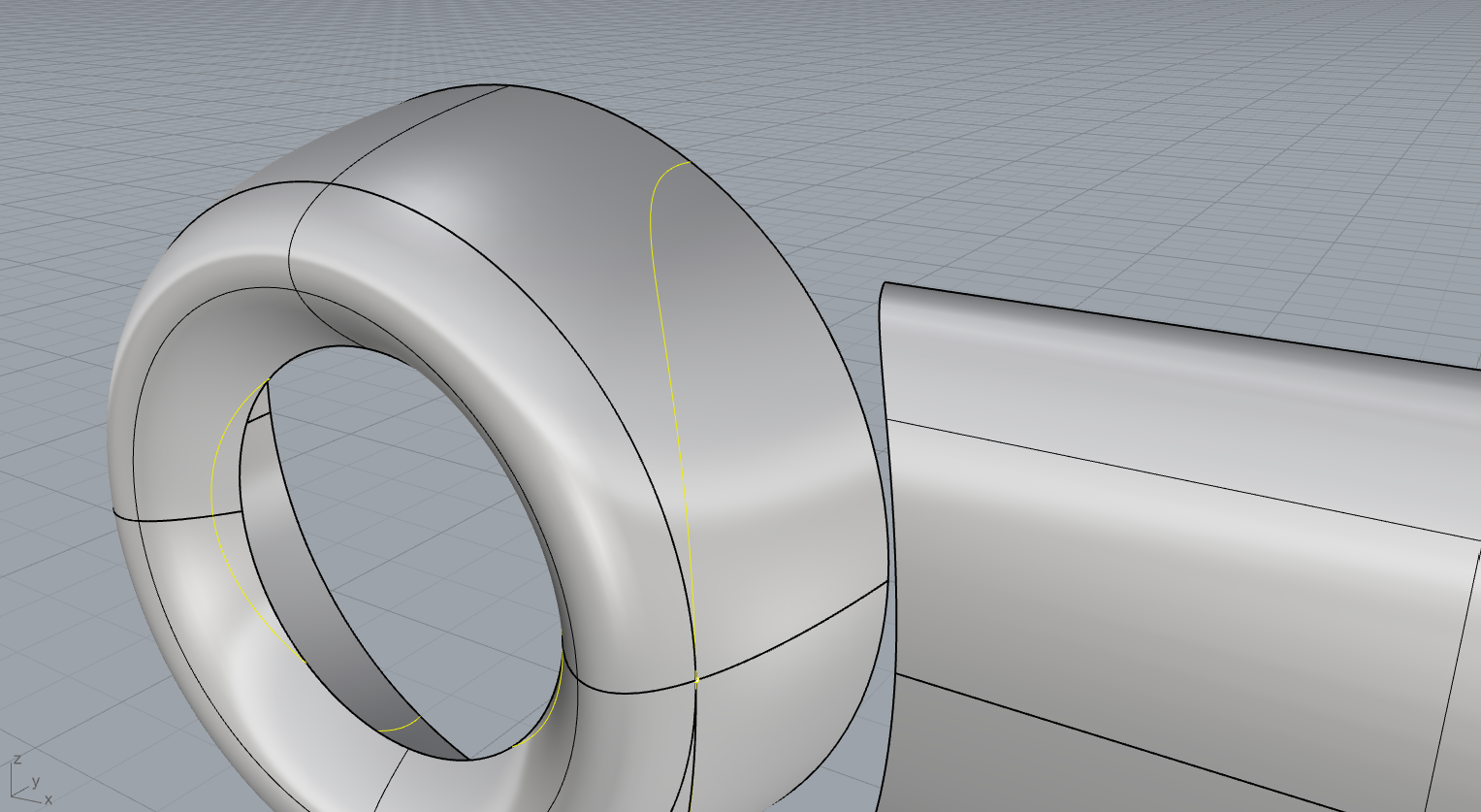
I will also repeat my statement about the adjacent surfaces at the middle. They must not be G2 to each other, because G2 makes them too smooth and therefore can’t follow the G1 tangency of the adjacent surfaces (the round body and the straight extruded body). This is why reducing the G2 to something like G1 or G1,5 makes it visually more proper.
By saying G1,5 I mean something in-between G1 and G2, i.e. G1 with some improvement in the 3rd row of control points, but still lesser than G2. By saying G1,95 I meant a continuity that’s visually G2, but of course it’s done by eye, so it’s never a true mathematical G2.
Nevertheless, the patchlayout proposed by all is the correct one. If all surface intersect in a clean way (=theory shape), before the fillet blends are applied, the curvature flow will be very good. In class A modelling we consider a numerical value of tangent dev at 0°05 as G1. But as it had been said, this is no class A skin, so don’t be more holy as the pope will be. All did a great job!
Thank you all for your wonderful examples. @Mark_Landsaat, @sgreenawalt, @germans, and @Rhino_Bulgaria all certainly nailed the look I was aiming for but I’m embarassed to say that the individual steps taken to achieve those results is still a little lost on me. I can follow in the macro terms, but I feel like there are small things I’m missing because my own attempts to replicate result in a transition surface that becomes impossible to MatchSrf effectively on all sides.
@mark_landsaat, my main question for you is what steps you took to develop the curves which trimmed the wheel section? Did you DupEdge the body section and then scale it up and project it onto the wheel section or something?
@sgreenawalt Did you use your god tier VSR tools only for the analysis part, or in the construction process as well?
@Rhino_Bulgaria your screenshot workflow is helpful but only to a point, unfortunately. Some questions for you:
Couldn’t that workflow have been initiated from the original file rather than Sky’s?
What’s the reason for aligning the 2nd row of control points in the middle steps, why isn’t the first row sufficient?
I’m not sure what’s happening in that step “Creating another cutting surface…” in which there seems to be a planar surface perpendicular to the wheels in the background. What’s that for? What’s it cutting…?
In the next step, when you say “merge this edge that was previous split”, equally difficult to tell what you’re referring to…
Try as I might, enabling “Planar sections” never seems to work for me. In my attempts to replicate your workflow, running BlendSrf between the two edges always results in a surface that is non-planar for the first row of control points. Planar section enabled has no affect on this outcome. Super strange. What might I be missing here?
This “remove multi knot” action is new to me. What’s the general logic/pattern for when to use this? How is this different from say, running Rebuild?
Here’s an example of me trying to follow @Mark_Landsaat’s workflow, and failing:
First, I create a set of points to indicate exactly on the wheel surface where I want to cut…
Created an ellipsis that would be around the right size for what I’d want to cut into the wheel section
Projected that ellipsis onto the surface…
Split the surface, removed the unwanted portion…
Tried running BlendSrf with Planar sections on.
As you can see, it’s definitely not planar. The surface is concaving inwards no matter what. I feel like this is the simplest workflow of all the options presented to me and even this attempt of mine is failing, ha
For my approach, I found the theoretical intersection between the areas that you are trying to blend and I trimmed it back with a pipe that runs along the intersection of the two surfaces that you are trying to blend. See screenshot as well as .3DM, I left the intersection curve and the pipe in the file, but did not blend it.
For what it’s worth, I believe @Rhino_Bulgaria trim solution is better than mine. His trim follows the shape more naturally, because he’s using a copy of the surface. This has a much better relation to the original surface, than the pipe does.
If BlendSrf doesn’t do the trick for you, you can build two blend curves first and use Sweep2. As always, there are multiple solutions.
I use the surface edges as my inputs for BlendCrv. I only care about shape at this point - not whether the curves sits on the surface. Once you feel you have the right shape, you use Pull to suck the curve onto the surface as a trim. If you save the original curve you can go back and edit it if you don’t feel the shape is what you want. For me I feel like this is actually easier and offers greater control than using a surface as a trim. Just another way to skin the cat.
BTW to answer your question the surfaces I made were generated at first with VSR but then matched/tweaked with MatchSrf.
Thanks again Sky. I have quite a few questions from your video:
You say using the loft is a trick (eg: use it if you can get away with it). Any reason you’d prefer this approach when available? And assuming you can’t loft for some reason — is the de facto move always EdgeSrf, as your video series really emphasized?
Assuming EdgeSrf is the de facto approach, should I safely assume the only steps remaining would be to (1) draw the final connecting line at the top (2) run Match on both ends of both lines so they’re curvature continuous to the surfaces, then (3) run EdgeSrf on all 4 lines, and then finally(4) MatchSrf on both sides of the new surface? And alternatively in the beginning, I could have simply generated the bottom and top connecting rails safely by running BlendCrv at the bottom and top of the two surfaces?
When you do loft, why aren’t you enabling Match start tangent Match end tangent? When I turn those options on, it seems like the initially lofted surface starts off in an even more ideal state. Is there some gotcha I’m missing if I do that?
When running MatchSrf, when/where/why do you choose to match isocurve direction and when do you not? Is there any reason you’d ever NOT match isocurve direction for a transitional smooth surface blend like this?
When running MatchSrf, why do you choose Match edges by closest points on the left side match, but not on the right side?
Loft works nicely in situations where you’d normally use BlendSrf because Loft will not create overly dense surfaces like BlendSrf will, and it has the added advantage of not needing to even bother drawing edge curves like you’d need for Surface From Edge Curves. It’s just another way of getting things started, another tool and so if the situation doesn’t allow for it, sure use Edge Curves.
Slightly hard to follow your second question, but I think you have it right.
Well you can’t use the tangent on the trimmed side, because you want to use the curve not the edge. Also, sometimes I find that Rhino places the spacing for the points between edges in slightly less than ideal spacing - by using Loft and then bumping up the degree from a straight loft you often get better point distribution across the surface.
Did you watch my MatchSrf vid? I go over those options and a bit of the thinking lots in that one.
Same with that last one - it’s all in my MatchSrf vid.