Hello Forum, just working away on a large urban landscape project, lots of bespoke granite stoneworks involved. I’m trying to understand why a fillet fails, screenshot and sample file attached.
(I have managed to create the piece I need but would be good to understand why my 1st approach failed) tia ![]()
Fail Fillet.3dm (874.8 KB)

Hi @milezee
I’m guessing you made the original top surface using the Patch command? If you explode and untrim all of the surfaces, and then run intersect between the sides and the top, you will see that the sides and the top don’t intersect one another fully - There’s only a very partial overlap (marked in yellow on the screengrab). You probably shouldn’t have been allowed to join them in the first place, but anyways…

If I’m right about you using patch, my best advise is to only use patch as the very last resort and that if you do, make sure that all surfaces have plenty of overlap for trimming it all back.
But I’m just guessing here, so please correct me if I’m wrong. The best way to create the top surface is to use EdgeSrf or Sweep2, which I guess is what you did on the working version.
If you insist on using patch, make sure that you use enough spans - in this case, 50x50 seems to work.
HTH, Jakob
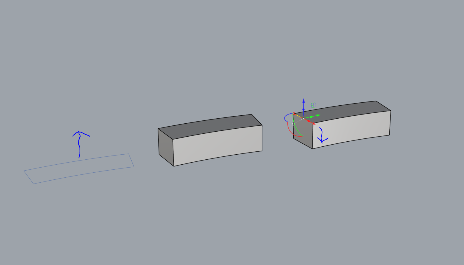
Hi Jakob, thanks for chipping in. I forgot to mention my method, apologies. No, no patch command. I extruded the base profile 250mm, then sub-selected one edge and -100 with gumball, screenshot attached, tia
Ooh, that’s interesting! So it’s actually Rhino’s own doing! @pascal - I think that might be worth a bug report! Just tried it out using the curves in OP’s file, and indeed; extrude, move edge down, fillet edge causes the end trim of the fillet to fail.
-Jakob
1 Like
Don’t do this, it is a recipe for failure. Rhino’s solid editing tools are not designed to be used in situations where there will be non-planar results - it then has to automatically “patch” the planar surfaces that have become non-planar in the process and often fails. In this case it simply introduced an out-of-tolerance edge (0.003 while your file tolerance is 0.001). The proof is if you reduce the file tolerance to 0.01, the 16mm fillet succeeds.

I can only recommend constructing this object in a different way that does not involve solid edge editing that would produce a non-planar surface. For example, Extrude the two curved sides up to the lower height and then move the opposite vertices up to the upper height via SolidPtOn or sub-object selection. Then make the planar ends with PlanarSrf, the top surface via Sweep 2, join all and Cap to make the bottom surface.
1 Like
thanks @Helvetosaur, thats one way to do it yes. Adjusting the file tolerance in my template might be an option too, I can’t see a reason why most of our project work would need 0.001 when 0.01 would work for what we do. I probably need to understand tolerances a little better within Rhino. thanks for the input ![]()
While that might be fine for what you do, independent of that I can’t guarantee that the procedure of moving the edges as you showed will work even with with a lower basic file tolerance, it might just result in an even larger out-of-tolerance edge at that spot.
1 Like