Hi All,
I’m trying to grasp the element definition and usage in visualarq.
My problem (feel like a noob) is that I don’t get the second point/rotation prompt and I can’t fathom how to define it in my grasshopper definition.
I get the insertion point as it should but I’d like to align the element along a curve and without the second point I can’t.
Furthermore… would it be possible to define more complex geometries for the definition of generic elements? i.e. create an element based on a curve that needs to be selected?
Thanks in advance!
Hi Miguel,
I wonder how is your definition that you can’t define the second point of insertion that defines the rotation of the object.
You can also do what you request, about having a curve as a parameter. The current drawback is that this curve must be selected after having inserted the Element, which is defined by an insert point. (We will change this in future versions and accept curves or surfaces also as insertion methods).
I’ve developed a simple example. But just notice that in this case, the insertion of the object must be aligned to the X axis, otherwise, the adjustment of the geometry to the curve won’t fit properly.

Hi Francesc,
I made a simple example like that to get the hang of it and that is what I expected but the prompt for the object rotation doesn´t pop. The object gets the point and then comes the prompt for a following object.
I´ll try again this evening and will share the file or video if the problem persists.
Thanks a lot!
Hi Miguel,
I suspect that you have a Point referenced in the GH file, and you are selecting it when you create the new style. This option is useful when that referenced point is acting on the final geometry (in VA templates, the “Elevation mark” annotation style is created that way, where the referenced point gives the elevation coordinate value. https://youtu.be/UTqIEOVsKpg )
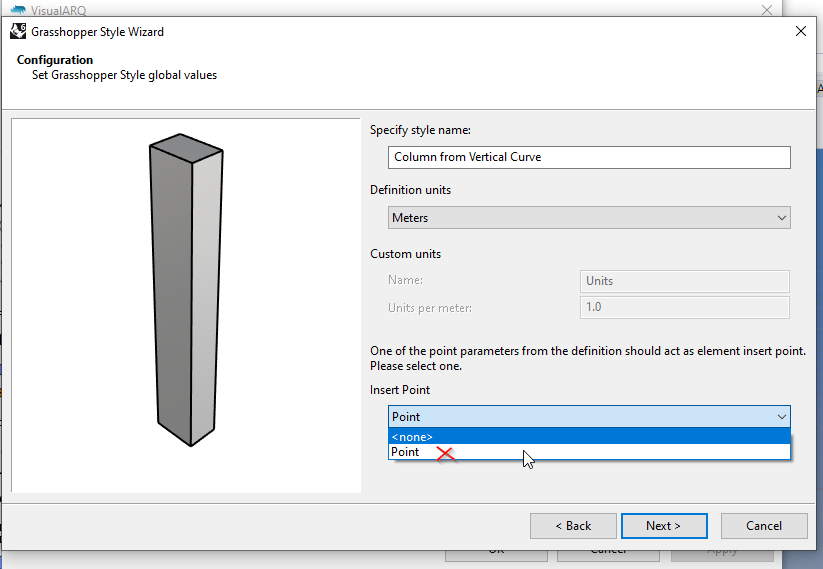
Just select the “None” option as object insert point, that way you will be free to insert it anywhere with the desired rotation.
1 Like
That is exactly the problem.Thanks!!
After solving the insertion rotation, I tried using the curve as an insertion reference. The problem then arises as the element prompts for an insertion point and rotation and this point and rotation override the curve reference… Is there a way to “correct” those overrides?
Hi Miguel, when you insert the Element object, you need to define the rotation oriented to the positive X Vector. This is how the definition might be created. Take a look at the previous gif in this thread, with the slanted column. Later on, when you select the curve as a parameter, the Element should orient properly to it. If this is not working in your case, please share the definition so I can better understand the situation.
1 Like