Appears that the path is long (and hilly).
Mesh_MeshBoxFromGeomBase_V1.3dm (1.8 MB) Mesh_MeshBoxFromGeomBase_V1.gh (122.3 KB)
BTW: Coding is like windsurfing: in order ro learn waterstart you should go into the deep without the uphaul rope.
Appears that the path is long (and hilly).
Mesh_MeshBoxFromGeomBase_V1.3dm (1.8 MB) Mesh_MeshBoxFromGeomBase_V1.gh (122.3 KB)
BTW: Coding is like windsurfing: in order ro learn waterstart you should go into the deep without the uphaul rope.
@PeterFotiadis Yes I agree but I need to understand the basics first , and right know , I still cant write a correct code at all. thank you for the box code but this is supposed to look like this though?
I have created a c# code for the box made with triangle faces from points but I can’t make it work , can you tell me where I am making the mistake ? Also I was trying to calculate some angles but the c# code is not working properly I am not sure how to do it .
box2.3dm (20.8 KB) box.gh (9.0 KB)
thank you for your help very much!!!
In R5 yes … but used Methods are obsolete in R6: As I said I don’t work with R6.
I’ll look on your stuff after FP2 in Abu Dhabi (forza Lewis) - assuming that your R file is in R5 format.
BTW: You got it 100% wrong: forget points > you should make a Box first
Plane plane = new Plane(orig, Zdir); // --------------- define orig and Zdir
Interval intvX = new Interval(-X,X);
Interval intvY = new Interval(-Y,Y);
Interval intvZ = new Interval(-Z,Z);
Box box = new Box(plane, intvX, intvY, intvZ);
Point3d p = box.GetCorners(); // ----------------- see SDK for the order
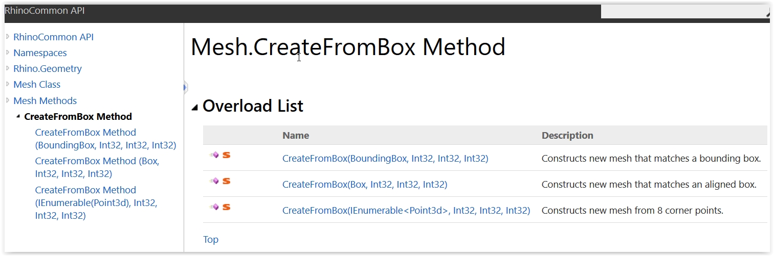
… and then get a tri/quad Mesh out of it (the last C# provited is using an exposed Method for that but you can do it the analytic way as well [but why bother?]) instead of trying to deal with a collection of points where only you can tell the order etc etc.
@PeterFotiadis Hello, I have managed to create the box with the mesh triangles, but I didn;t understand the way you showed me in rhino common , I did it differently, but I couldnt figure out how to calculate the angles and connect the edges …
box1.gh (10.9 KB)
box.2bdm.3dm (35.3 KB)
You are 1M miles off target. Why? well … for many reasons but the Numaro Uno is that you haven’t read the #^%# manual (the C# book) 5 times. Meaning that if you continue that way you’ll become a pro around Y 2525.
Note: most amateurs in our trade (AEC) believe that coding is the thing that would help them to do geometry. Amateurs, that is.
Anyway:
box1_V1.gh (15.5 KB)
BTW: Forget meshes and think: given a “template” of something (say a mesh) we do something (say a truss). So assume that you have the geometry on hand in terms of a truss axis collection (i.e. some lines in 3d space). What serves this without connectivity (and clash checks?). Zero that is.
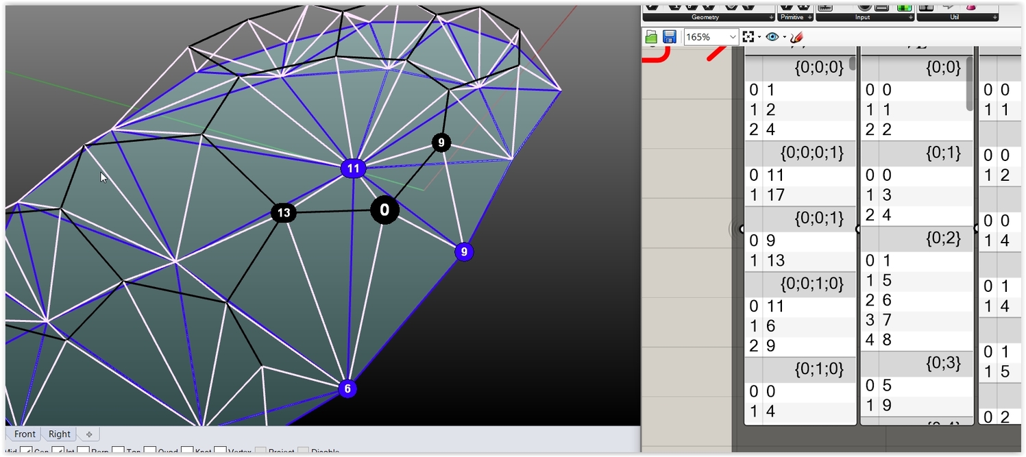
See and decode what these 3 images can tell you (blue: the bottom layer [from mesh], black the top, white the W content):
Moral:
box1_V2A.gh (119.2 KB)
@PeterFotiadis Thank you very much for helping me to understand how it works …I started learning C# last month …
I know, I have to work on it quite a lot - I struggle to understand how the program works you know …
So in order to keep the connectivity between vertices/ or other elements we create Data trees?
[quote=“PeterFotiadis, post:25, topic:92679”]
What serves this without connectivity (and clash checks?). Zero that is.
[/quote] what is clash checks?
You are certainly very very good and very experienced, good that you are around ![]()
A DataTree is a custom (to GH) thingy (done by David) that allows you to handle nested collections: is kinda a Dictionary of Lists. Is a good thing if your world is GH not a good thing if (1) GH is just an other app used in the practice AND (2) everything is done via code (as is the norm these days).
Connectivity is a way to correlate Lists of integers (i.e. indices of Items in Lists). Connectivity may refer to a single List (for instance vertex to vertex connectivity) or 2 Lists (for instance face to vertices connectivity). The last branch dimension is the index of the item in question and the branch content is the indices of the items related (or connected) with that item.
This means that we have a collection that is kinda a sum of Lists … i.e. a DataTree.
So … connectivity allows us to assemble a truss on site … but that’s the easy part:
In real-life trusses are not lines: they are solids (tubes, sleeves, cones etc). Meaning that for random/irregular solutions (like the one from a relaxed mesh to a vault) you may encounter “contact(s)” (i.e. clash) between solid items when an axis-axis angle is smaller than the one that is allowed for a given member topology at a given node. This is the main reason that we need connectivity in order to check (via trigo, NOT ccx events) situations like these. So: geometry is nothing, validation of the geometry is everything.
The attached is an entry level demo on mesh connectivity matters using your box > mesh idea. A mesh is a collection of vertices, edges and faces meaning that the possible connectivity trees are 3*3 = 9 (the C# does 7, you should one day do the rest 2).
For a truss connectivity … we use more or less “similar” ways (but the connectivity trees are 4 dimension trees).
Mesh_FromBox_AnglesConnectivity_V1.gh (121.5 KB)
That said a random parametric truss is the most challenging task known to man: you’ll see the reasons soon. For the moment study these (more or less close to a real-life MERO KK struss system):
BTW: If you like an outwards truss deployment on a tri-mesh (i.e. hexagons) see a classic MERO take on that matter (but I don’t like EFTE by any means).
MERO_EdenProject.pdf (5.1 MB)
Moral: Forza Lewis.
@PeterFotiadis " Avoid academic thinking " that’s a good one!!! Thank you for your tips. I am sure they will come handy in the future! In my opinion, Eden project is very succesfull. ETFE eeehh I am not very fun either they have short life span and its not the solution for most designs but for Eden project is perfect. I want to ask a quick question , if we want to populate a 3d element on a surface how can we do it in c# code I mean … obviously we use loops and arrays but I am not sure how it can be done on a 3d surface … lets say I have a sculpture and I want to add some shperes how can we go about it?flower petals.3dm (289.7 KB)
Thank you for all your advices…
You can spread points in a BrepFace (general case) with a variety of ways (random, by dividing the underlying surface [and filtering by face containment] and/or others), define suitable target Planes (orig: pt, Z: surf normal), manage their X orientation (that’s tricky) and then use a Plane to Plane transformation on a copy of the object (amateur’s solution) or an instance definition (the pro way).
The object should lay on a well defined (say: “standard”) from Plane i.e. in most of cases the Plane.WordXY (always define your instances that way).
BTW: Plane to Plane (using instance definitions) is the way to place solid members in a truss (you’ll need a sleeve, a cone and a min size tube object - like in the above pics). Same for the envelope … but things are more complicated in real-life. See what an Eden node is:
BTW: In a MERO KK system the smaller the ball the more the focus is shifted towards sleeve to sleeve clash checks. The opposite happens when the ball is big (focus on tubes) but that yields to some aesthetic havoc.
BTW: ALWAYS before doing anything fully resolve the nuts and bolts of that: the so called bottom to top design. The other way is the best recipe for disaster (or a waste of dollars for absolutely no reason). Is kinda designing an ICE engine without having any idea about what cranks, pistons, rings, conrods, timing chains, camshafts and valves are.
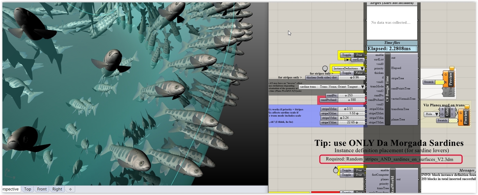
After some months (or years) remind me to send you the notorious Sardine collection of C#'s that do Sardine related transformations (Plane to Plane and others) using instance definitions (out - you guessed - of Sardines). That said these work only with DaMorgada Sardines (due to a bug).
Get some simple stuff:
Transform_PtoP_EntryLevel_ForAmateurs_V1.3dm (1.3 MB) Transform_PtoP_EntryLevel_ForAmateurs_V1.gh (124.4 KB)
And the proper thing:
Transform_PtoP_EntryLevel_ForPros_V1.3dm (5.3 MB) Transform_PtoP_EntryLevel_ForPros_V1.gh (154.4 KB)
@PeterFotiadis thank you for your reply.
I will be probably annoying asking all these questions but I dont fully understand your codes. So an instance as I understand from using 3ds max design its a copy / clone of the original . When you change the instance then all the instances change as well - they share the same properties , is it the same with rhino instances? From c# components it looks that the instance is a string? no? so the properties of an object are saved in a text file? I opened the first file amateurs one but it does some strange things like populating the geometry around the surface and not on the planes ?
I dont really understand how the pro works … Why you have several surfaces to choose as a list to make a plane? why you have all of these voids in between?
An Instance Definition is something that acts as a cookie cutter meaning that if you place one is in fact a trans matrix related with the cookie itself. So this makes a real-life file light (think a truss with 100++K solid members that is quite ordinary in stadium designs etc). Plus of course any change in the cutter reflects to all related cookies. In real-life we use hierarcies of Instances (the so called Assembly/Component approach that works in tandem with the bottom to top design mentality).
An assembly is a void (with regard geometry) or not node that owns sub nodes. For instance an engine case geometry may belong to the engine assy while 8 pistons may belong to the pistons assy that own piston rings etc etc.In the old days no AEC CAD app worked that way … but never is too late: these days they try to play catch up with the MCAD Kings (CATIA and Siemens NX).
The pro places directly Instances in your doc (no baking required) instead of cloning the object in question meaning that you gain tremendous speed, a min file size and the ability to change all things at once. At placement time you can assign an attrribute to the Instance in order to find it later (deleting etc etc).So an Instance is - obviously - not a string (what a freaky idea was that, he he).
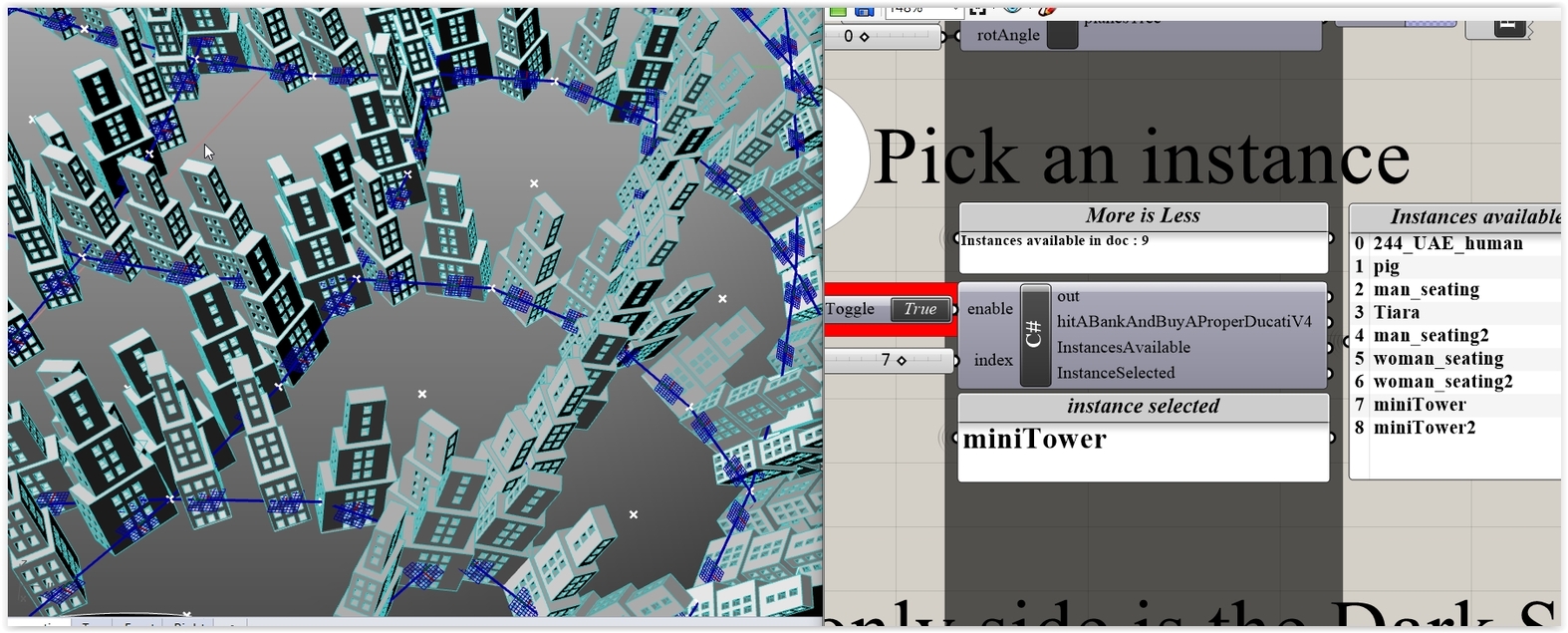
In order to place Instances you must have’m first: so this does the query and reports what’s available. If your file contains no Instances … well … the last C# does nothing since if you add null to null you get null (LOL).
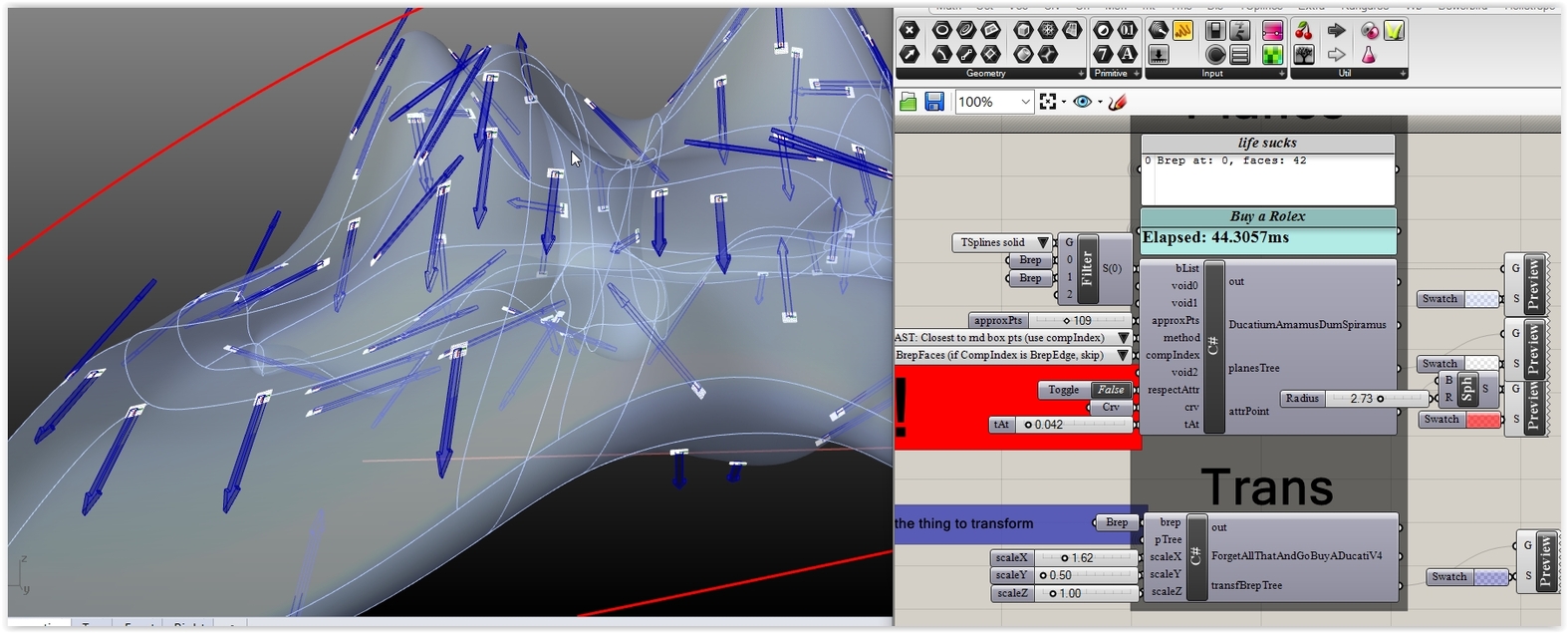
With regard the Amateur thingy (that clones the object) … well … it transforms the demo arrow object (is like an arrow in order to understand orientation matters) using planes that are defined with 2 ways on BrepFaces. Plus it rotates (an option) the Target planes in order to “point” (plane.XAxis) the attractor that moves around via the tAt value (see 2nd pic below).
NOTE: the fast option is using an “extended” Method that returns Normals either in BrepFaces or BrepEdges (hence the option provided). Add this line if you are curious about ComponentIndex matters:
So what do you mean with your comment? (strange things? where? when? why? )
That said if you do something via code you should ALWAYS provide a variety of test objects for more than obvious reasons.
That said voids in a C# body are used in order to get a well ordered/compact aesthetic result (I don’t like at all wires going all around the place). Plus voids separate inputs (in “groups” so to speak) for clarity.
That said if you can’t deal with these … just panic … and go read that #4$#%@# manual (again).
Moral:

@PeterFotiadis
sure … but you are using the panel to add it you are not using a brep or a mesh or a surface component thats why i got confused.
I think I have another manual for C# I have the C# code for Visual studio , I could n’t find anything in the market to connect with grasshopper. and c#… when I say market I mean Amazon …
Haha I want to cry and laugh at the same time ‘’ I m in a place where i don’t know where I am" it is flipping true! it sucks ! I am not damp i cant be cause i studied architecture hey!!!but learning C’# makes me feel stupid! I don#t get it at all :(. It is very frustrating…
Well … you should walk the walk then (BTW: for the last time: forget Internet (and GH), read a proper C# book, and when/if you are ready … well … do whatever).

BTW: Get an update … that can tell you a thing or two about why Instances is the only way to cut the mustard.
Transform_PtoP_EntryLevel_ForAmateurs_V1A.3dm (1.6 MB) Transform_PtoP_EntryLevel_ForAmateurs_V1A.gh (127.0 KB)
@PeterFotiadis please continue to encourage me …I need support outside of my circle you know!
I love the picture!!! hehe… I am the cat walking near dog hunters ohhhhh!
the reason …of me learning C # it is because I cannot work in the office designing brick blocks! This is not me for sure! It is not challenging enough , and it destroys all my artistic and AESTHETIC qualities , I already had and i developed through my architectural studies … Am I ready , I am for sure … but its because I never struggled so bad for something … it is like learning chinese for god’s sake… this is how i see it!
YES I understand the importance of an instance … it can be very very very handy … if you have a massive amount of the same elements and the file becomes massive and you are not able not even to rotate the thing without rhino crushing (yes I have experienced this madness). It is very scary !
So creating a “block” in rhino and creating an instance in C# its almost the same concept right?
can you correct this for me ? I tried to make a concrete origami vault … but somewhere I got wrong …origami concrete roof.gh (26.4 KB) origami - form finding.3dm (36.4 KB)
Insofar we’ve seen a way to place Instances that a given doc contains (visible via BlockManager). Creating them via C# is another matter. I’ll post some day an entry level take on that (some stuff is not for public eyes, mind). That said in real-life we rarely use non nested Instances. That said … well … for creating real-life objects (solids) that could define Instances later on you’ll need Feature Driven modelling (R is not the app for that by any means). Find a friend who’s expert in Microstation/AECOSim and ask him to explain what a Model is and what’s the difference from a Cell.
That said a US based friend once send me a R file (some challenging truss) for inspection and STEP 214 export tests. File was 500MB. I’ve send him back a 1.2MB file containing the very same items (and the ability to change anything in a split second).
PS: Your origami (I hate these things) is R6 + K2 for R6 : adios amigos. So I can’t help you on that one but Daniel has posted various origami defs in the past.
So you have stuff like this eh? If so answer the mother of all questions: Ferrari 250 GTO or Aston DB4 GT Zagato? (have 20-40+M on hand for these).
Why OR, just do AND…
I don’t like any of these cars … sorry … its just not my style haha. But the red one is better for sure.