This cobbles together some bits used previously to explore the scarf joint. Rather simple until you get into its variants.
Scarf Joint With A Wedge has two wrinkles: 1) the scarf surfaces interlock, requiring two levels on each block and 2) the wedge (or pair of wedges).
The best example I found was this one: Undersquinted wedged scarf joint

Complicated! So I looked at an easier one: Post or Rafter Scarf Joint

joinery_2019Oct13b.gh (45.4 KB)
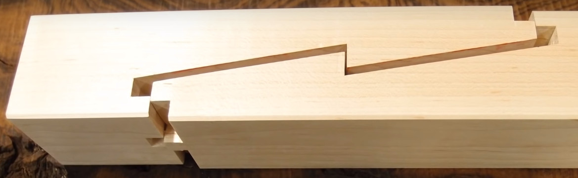
P.S. More variants of the scarf joint - precise and invisible, fine craftsmanship!
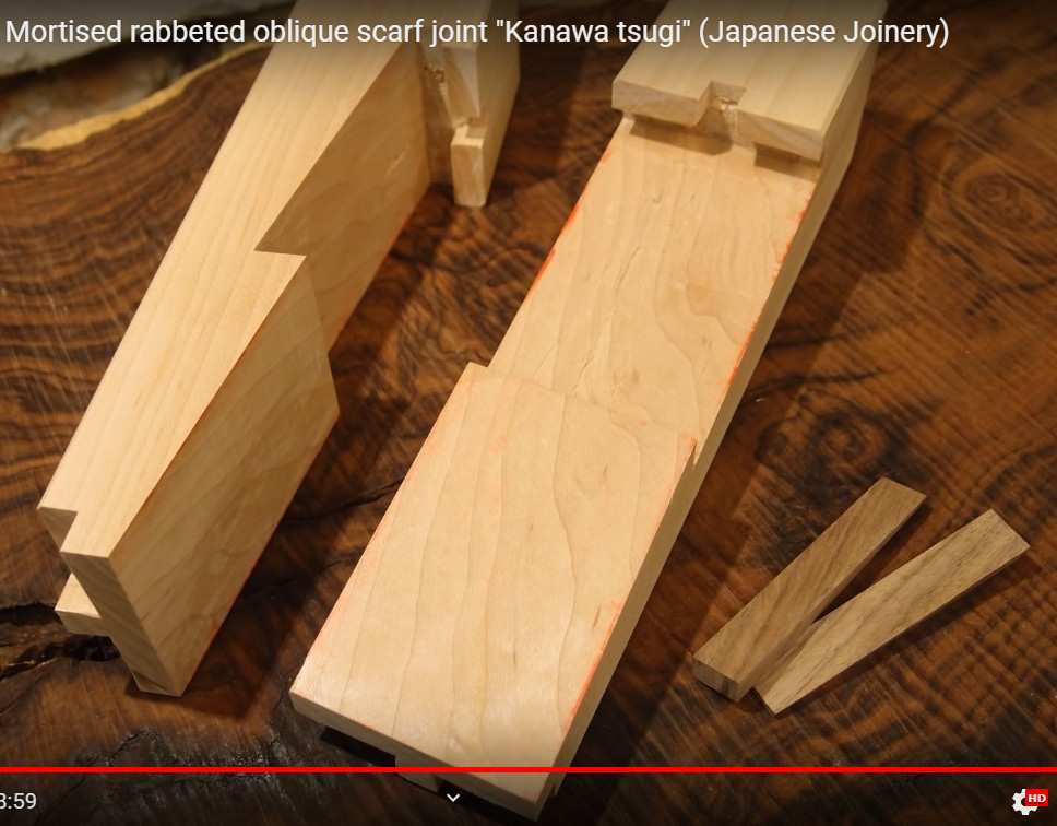
And with hidden pegs:
