Mechanical - Best performance?

OK, a question for you experienced mechanical engineers out there :

Q: If I didn’t have to care about standard components or manufacturing cost, which solution of A and B below would perform better in transferring torque, the parallel or the tapered wedge(term?) as illustrated below? (and how would force vectors illustrate the relative difference, if significant) :

Edit:


Q2: For example, should I be concerned about the stress near the “inner corners” on the axle groove being worse for B than for A, or insignificant?

Q3. Also, if the outer ring would have only little bigger diameter than the top of the “wedge”(term?), say 20% of the height of the wedge, would alternative B be significantly more beneficial in that the force vector at the contact point would start more aligned (tangent) than A?

// Rolf

If you have any concerns about the torque capacity of the key you should be using a tapered joint (perhaps with a key) or a spline joint.

I doubt the difference in stress capacity, etc between your two key proposals is noticeable, and the tapered outer slot for the “wedge” key would be much more difficult to manufacture than the parallel sided slot.

[quote=“davidcockey, post:2, topic:41794”]
concerns about the torque capacity of the key you should be using a tapered joint (perhaps with a key) or a spline joint.[/quote]
In my special case I can use a maximum of two key’s placed diagonally on quadrants (is “key” the proper term for this joint in English? In Swedish we use the corresponding term for “wedge” (“kil”)).

[quote=“davidcockey, post:2, topic:41794”]
I doubt the difference in stress capacity, etc between your two key proposals is noticeable, [/quote]
If so I’d be happy. :slight_smile:

[quote=“davidcockey, post:2, topic:41794”]
… and the tapered outer slot for the “wedge” key would be much more difficult to manufacture than the parallel sided slot.[/quote]
In my special case manufacturing cost wouldn’t matter much, and also the outer ring would be split radially in two or four pieces.

What I absolutely want to avoid is having the key tend to twist out of the inner groove, and the outer ring being bent/pressed outward by the key (into an oval shape) due to the torque forces.

I should have drawn the typical ring thickness to be around 10% of the axle diameter (the ring was drawn a bit too thick here). Updated picture:

// Rolf

OK. With the reduced ring thickness we really are getting into actual mechanical engineering and out of the hand-waving realm. You need to be pretty specific about shaft and ring dimensions, material, maximum expected torque, cyclic torque max and min, cyclic frequency, etc. Then a mechanical engineer would do a FEA analysis and make recommendations.

If you can hold the keyway depth to less than 20-30% of the ring thickness and the wall stresses to 5-10% of yield you can probably guesstimate successfully. At the 10% level you should probably radius the bottom corners of the keyway.

People have been building machines for a long time with this kind of joint design and it has been successful because they are considerably over-built for the application. With 20th century weight sensitive designs came much more detailed analysis and more sophisticated joint designs to choose from. If you can get by with 19th century designs you can eyeball more.

1 Like

No “hand-waving realm” here since I was asking for a comparison between two different principle designs (pros and cons kind-of-thing, you know).

The design I’m pondering on isn’t in reality a regular simple axis & ring-thing. Instead there are many other constraints not shown in the picture which lead to my questions (for example, no direct contact between the key and the ring-material, instead there’s a bearing between, and hence it is of interest how the contact surfaces are aligned, that is, parallel or tapered).

So no, comparing two principal designs does NOT take specific numbers, that’s the very point with comparisons in general. In any context, philosophical as well as physical mechanical.

Edit: BTW, think of the axis diameter as 150 mm and the ring as 15 mm thickness. They scale up together. Steel.

// Rolf

Hi Rolf

Here are my 2.5 ¢ (CDN) to your predicament.

Q1
Providing the distance “d” is the same in all instances, all designs are going to transfer torque the same way. The distance “d” will dictate the shearing plane that will size up the key’s width and length, to withstand a torque X at a safety factor of whatever you can afford. From my own experience here is what I think of all options:

Design A
It is widely used across industry because of ease of manufacturing. You can cut the shaft (axle) with a cylindrical end mill and the key channel in the outer ring with a rectangular broach. The keys themselves are cut to size from standard stock bars.

The problem with this design is in case you are using loose tolerances (needed for ease of assembly), it will lead to a small play of the outer ring on the axle, which in the long run will end up shearing up your key. The key starts to slide in two different directions exactly at the shear plane. This design had given me headaches many times when trying to replace the key.
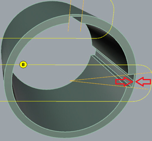
Design B
Making the right size key slot becomes an art. If for instance on the outer ring you use a broach to that profile and you don’t hit the sweet spot as marked “?” in my picture, you either have a play when you go too deep, or you cannot install the key if you go to shallow. The shaft is not that critical as you can always use a tapered end mill and cut a deeper channel.

Design C
If this was my project I would use this design. This way the cutting of the outer ring key channel does not need to be that precise anymore. To avoid the key moving at all, I would hold it to the shaft with a screw.

Q2
In regards to the key channel in the axle, I believe the tapered design is slightly better than the straight design. Why? Because the tapered key channel side walls are wider than that of the straight channel, and also the distribution of stresses to that side surface would be rather perpendicular to it (slightly better condition than on the straight wall).

Q3
I don’t understand it fully, but I think if this is a scaled model, then this outer ring channel is not meant to last. Your keys, no matter the design, may end up ripping thru your ring.
If you follow my picture, the meat on top of the key in the ring is thicker that the depth of the channel in the same ring and that way I know if anything goes it will be the key and not the ring.

Regards
Costel

2 Likes

Thank you very much for your reply. It was very informative.

Because of various constraints which I evaluated only after my first post, I came to the conclusion that I can only possibly use alternative A or C. With this guidance I will go for alternative C (I was just about to start doing the Grasshopper definitions, so your reply came very handy in :slight_smile: ).

Regarding manufacturing methods, I have quite some experience from the machining (sub contractor) industry in Sweden. I’m not myself a engineer though, but I made many parts for ABB Robotics, the defense industry and the mining industry (often spare parts would take to long to order from the USA and… ah, never mind), including reaming key slots for huge parts for those mega machines (Bucyrus, mega size CAT trucks for the AITIK mine, etc).

I will go for alt. C. And again, thank you for your elaborate answer, it was very valuable.

Edit: BTW, with Q3 I meant the thickness of the “meat” above the key to be about 20% of the total thickness of the ring (say 3 mm for a 15 mm thick ring).

// Rolf

Just a thought, how about the key being tapered either side? That’d lock it into both parts without the need for a screw. The ‘only’ problem being manufacture to tight enough tolerances and then assembly with a very large hammer…

Hi Rolf

I think I got Q3 the first time around. I don’t know much from you pictures as to how this is assembled, but if this ring is not the inside bushing of another gear or pulley, then I would not make it that thin. First picture shows (again, as I would do it) a scaled model of the key, taking into account the shaft if 150mm and the thickness of the ring is 15 mm. Screw can be M6 or M5.

Notice the fillet in the corner of the key-way in the ring. I recommend it in your case very much.

Second picture illustrates the broaching of key channel.

Regards
Costel

Good non-analytical explanation. If the applied torque is at all cyclical and not enough “meat” is supplied outside the key slot, the ring WILL crack by fatigue. If, as you say, the ring is captive in some other ring this may not be a big issue but if its not then maybe a string should be wrapped around it. :wink:

@RIL You never said anything about the torque to be transmitted.

@AIW: I’m drawing this with Grasshopper and it will scale to whatever torque needed. All dimensions can be set with drawbars (diameters, ring thickness, fillet radii etc.)

And yes, rings are on top of rings, in four layers. And no problem adding thickness as needed. This post was only about the choice of shape of the Keys.

Regarding torque: I’ve got one inquiry asking if the design would withstand 110kN torque at 720 rpm.

I answered yes. of course! … :slight_smile: (I actually didn’t answer as of yet, but final design is a completely different story. I’m only roughing out a basic idea so far).

Remark: I have not even hinted yet what kind of thing this really is, and from the pictures one cannot deduce it because the real shape it looks completely different. If it wasn’t confidential I would of course have shown what this is all about, but…

@Costel, yes, no problem with the material, some FEA analysis will tell how much material thickness to add to the rings. There will be two Keys on each layer.

The reamer… gives me shivers. I actually made a huge cogwheel (~1500mm diam) with a huge reamer machine a long time ago. It took almost a week (the copper mine stood still, waiting, kind of). That was in the late eighties. Those were the days.

// Rolf

1 Like