Hallo, is there anyone who has ever done a hullform of a J-class sailing ship in Rhino?
I’m having troubles with the extending of the hullform behind the rudder. So the part where there is no more keel.
I aproched it in several ways, and have found a way that works, but maybe there are other ways.
I would split it into 3 parts.
- Main Hull surface
- Keel surface
- Fillet between the above
I’ve done something similar for a pilot cutter model recently (albeit not in Rhino) - see below…

2 Likes
Thanks for your replies.
I am going to try Rob’s proposal as well. See or I’ll have enough control on the form. I do see possibilities.
First I tried 10 sections and added extra sections between the top and foot of the rudder to get a straight line for the rudder stock, but then the distances between these new sections compared to the other sections are so different that it is hard to get the lines fair.
Then I tried the rapid hull modelling, but there the same thing happened. Alltough I got rather far.
Added is my third try. This time I started with a mainframe, duplicated that fore and aft, and moved frame 3 and 5 (we start counting the frame numbers from aft to foreship) to the top and lower side of the rudder.
Then I started moving the frames in topview to the sheerline, so they are partly moved over the centreline.
After that the sections are changed. I’m using Orca 3D so it’s easy to see what a change is doing.
The last step is to cut everything over the centreline away, which leaves a half hull.
Wish you all the best for 2019.lijnen Shamrock met 11 spanten.3dm (295.3 KB)
Oooooh no, I don’t like that way of doing it at all.
Try this -
- Create a simple rectangular surface flat on centre line (from side view) and make it roughly the size of the hull part of the boat.
- Use the command Changedegree to add in a number of control point rows that will help you morph the rectangular surface into a lovely curved hull. Either U or V direction will lie fore/aft so start with about 5 or 6 for this direction. Try 3 for the other direction to start with.
- Turn the points of the surface on for editing.
- Use the move tool to move points (or sets of points) into roughly the right place, keeping the points in nice vertical rows - like stations.
- Check out how close to the sections you are.
- If more points are needed to hit the shape you are after then use the command Changedegree again to add in another row either in U or V direction (or both of course).
- Then use the move tool again to shift the points around again.
- To finish the bow - rotate the ‘station’ of points around to match the angle of the bow. Then create a couple of lines that intersect each other - one runs down the bow points. The other runs up the rocker (well not exactly, but runs between the lower most control points of the rocker at the bow). Take the bottom point of the row of bow points and add it roughly half way between where the two lines intersect and the first ‘rocker’ point. Then re-distribute the bow points equally on the bow line you’ve previously drawn (or use the moveUVN command via control polygon) and make sure the new bottom point sits on the intersection of your drawn lines.
It may sound like a lot of work but it’s really not. And it gives you a super nice controlled tweakable surface which the other surface creation commands can’t get anywhere near.
A super quick example is attached - not finished, I’ll let you do that. But use the same technique for generating the surface for the keel.
The blend between hull and keel may take more effort but try to keep everything single span for your own sanity!
Good luck!..and Happy New Year!
RM-lijnen Shamrock met 11 spanten.3dm (202.8 KB)
1 Like
Hallo Rob,
First of all, a Happy New Year.
I’ve got the impression that you think that the file I posted is the final form, but it was just a reaction on Stratosfear’s remark to post a file, and this was the last try I was working on.
I’ve still got to tweak, but don’t have the time to do so.
On friday I hopefully have the time to try your version which looks very clean and straight foreward.
Thanks very much for your advices.
Hallo,
Need some more help.
As suggested by Rob, I made a hull and keel both trimmed to make room for a filling surface that should at least be tangent to the hull and keel surface. See the attached file.
Blend surface doesn’t work because of the longer hull edge compared to the keel edge.
So I tried some sections and made a blend curve between the section of the hull and of the keel.
After that I split these curves at the surface edges and lofted them.
At first glance it looks good, but it is not possible to join them because they edges are not exactly the same.
Anyone got suggestions how to solve this?
The hull and keel surfaces are only faired by eyeshamrock.3dm (553.4 KB)
.
Hello - the trim on the hull is in two non-tangent segments - I’d make a single clean curve to recreate that trim. But once that is sorted out, MatchSrf with the appropriate settings should help. (Match by closest point, Preserve isocurve direction)
shamrock_Maybe.3dm (107.2 KB)
I added one set of knots to the transition surface to allow it to MatchSrf cleanly enough to the hull to join.
-Pascal
Hi Pascal,
What you did works.
Going to try to duplicate it on friday.
Thanks a lot.
Hallo Pascal,
Can you tell me step by step what you did? I tried all kind off differend ways, but it doesn’t work in my model.
I un- and retrimmed the hullform so it has one edge curve, but for MatchSrf I need 2 untrimmed surfaces, while both surfaces are trimmed.
And how and why have you put in a set of extra knots in the transition surface?
Hello - see if running UntrimBorder on the existing transition surface sorts it out - I do not recall but it could well be that I untrimed it - I don’t think in this case that it does anything to the shape of the border.
I added knots using InsertKnot with the ‘Automatic’ option - (inserts knots between each pair of existing ones) so that the matched surface would join to the hull - as is it was a little sparse - not enough control points to pull within tolerance of the hull edge. The Refine option in MatchSrf will also add knots if needed, but I find it tends to be a little, or a lot, overzealous in adding knots and I can usually get a lighter more even (knot-wise) surface by adding them myself and not using Refine…
-Pascal
2 Likes
Interesting comments Pascal. I hadn’t considered InsertKnot as an alternative to the Refine option in MatchSrf, but now you say so, it makes perfect sense. Care to elaborate on spotting conditions when to use one over another?
To Refine or not to Refine, that is the question…
Hi Matt - if I see an obvious location after a match where it needs more info (points) then I try to bracket that area with a couple-three knots - I try to use the MidPoints option in InsertKnot since it keeps the knot spacing uniform - most often I’m working with uniform geometry if possible. If that is not enough, I add a couple more. In this example, it seemed like there was a relatively even edge to match to - no sudden changes in direction for example - so one dose of ‘Automatic’ seemed like a good bet. It might be that Refine would have been fine (I did not try) but more likely is would have ‘heavied it up’ rather more…
I never use refine if the preview shows me it will overload (whatever that means at the time) the surface with knots…
-Pascal
There is one nice trick with the refine option in Match surface. When I have to use the command and need to refine the surface to be as close as possible to the target edge (or untrimmed area of a surface, if using the “CurveNearSurface” option), I usually set the “Refine match” tolerance to be 1/2 or smaller than the absolute tolerance of the scene. Quite often I notice that the “Position”, “Tangency” and “Curvature” options will refine the matched surface with different amount of newly added knots, so for example when I want to match the surface to be curvature to the target edge, but see in the preview that it will oversaturate the surface, first I use “Position” combined with “Refine”, then I run “Match surface” again but this time I use “Curvature” without “Refine”. This adds considerably less knots while the surface are totally joinable and visually proper when checked with Zebra or Curvature analysis.
1 Like
Hallo, I tried all the things you people propose, and after a while I get them working.
Because I could not get blend surface working between the hull and keel surface I made the third surface.
But is there a way to make blend surface working?
Hello - BlendSrf works, but you need to carefully set interior shapes and directions - in the attached, I used History, you can run the BlendSrf command > Edit in my file and click on the blue blend surface to see how the handles and points are arranged - does that get at what you need?
shamrock_Maybe_Blend.3dm (139.7 KB)
-Pascal
Note: Absolute tolerance changed to 0,001 mm. Surface isocurves are hidden for a better visual clarity. History recording is enabled. Modifying the white surface by its control points will result in automatic changes of the remaining surfaces and blend curves.
The Bulgarian way.3dm (3.0 MB)


Accomplished this in Rhino as well, see attached. Job was to recreate a Bermuda Forty from a poorly scanned set of ancient hand drawn hull lines. Tweaked the form such that the displacement and other hydrostatics matched the original within .5%
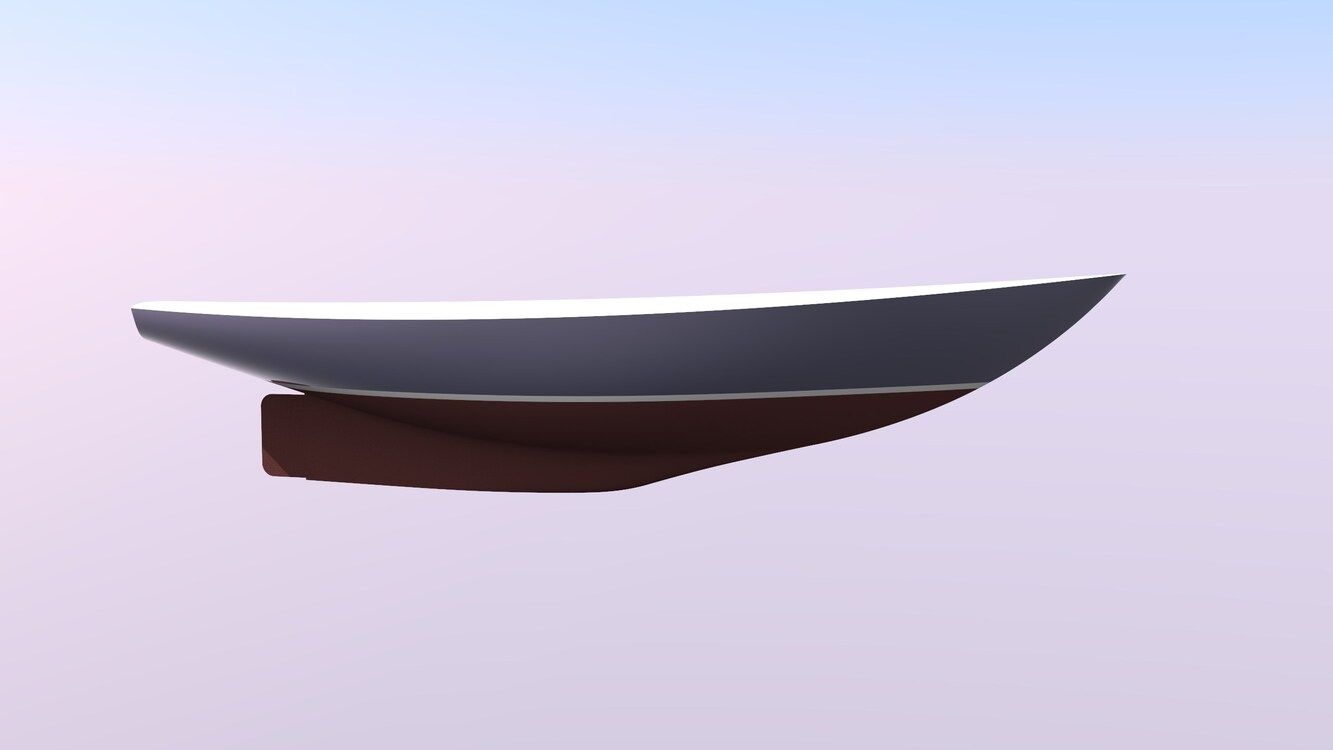


That keel looks too fat! Maybe foreshortened in that bow view but I know that hull shape well from scrubbing the bottom. How about an ortho body plan view or I’ll have nightmares?
All I can tell you is that I used a scanned digital version of the original hull lines done by Bill Tripp senior. And that the boat is a keel/centerboarder that originally had (I believe) a wooden centerboard that was likely fairly thick for strength purposes, thus the keel is a bit thick but likely over the entire length of a typical keel chord, the sectional foil would only be 10% or even less. I did this at the request of the owner who wanted a couple of hydrostatics and stability runs for his particular boat that was getting a new deck.