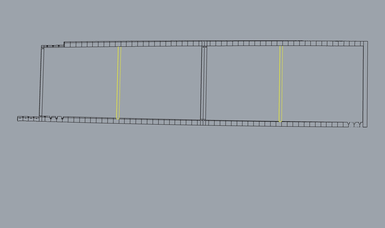
For the moment I found a bit of a work around simply converting the Brep into a Mesh (tried converting to surfaces before but that was even uglier), however this increases computation time and the result is not pleasing:
Hi @richard_schaffranek
Are you using clipping planes? Looks like intersection curves between the clipping planes and your geometry are being omitted. Check the sample I shared in this link, and let me know if you still have a problem:
no I am never calling the function AddClippingPlane(), I am constructing a Viewport from scratch (and for visualisation, I am also change the current Rhino Viewport to the same view). See initial post. And I also have been following the HLDParam in my debugging session, it never shows up with clipping planes.
Just a quick question, is the hidden line drawing using the graphic card? I am running the code on a laptop with a dual graphic card and I am not so sure which of the both the C# code is accessing if so…
@richard_schaffranek
In your code:
" VP.SetToPlanView(P.Origin, P.XAxis, P.YAxis, true);"
Where do you get the “P” from?
Also, the “geom”, is it a list of all geometry in the doc?
Also, you have “_Att” in “_objAtt.Add(_Att[objIndex]);”, is this the list of attributes of your doc objects? I did the following to get the 2, but still not sure what “P” is:
      var go = new GetObject();

      // Get Objects in document to compute Make2D calculation on
      go.SetCommandPrompt("Select objects to Make2D");
      go.GeometryFilter = ObjectType.Point | ObjectType.PointSet | ObjectType.Curve | ObjectType.Surface |
                          ObjectType.PolysrfFilter | ObjectType.Mesh | ObjectType.Annotation | ObjectType.TextDot |
                          ObjectType.InstanceReference;
      go.GroupSelect = true;
      go.GetMultiple(1, 0);
      if (go.CommandResult() != Result.Success)
        return go.CommandResult();
      var obj_refs = go.Objects();
      List<GeometryBase> geom = new List<GeometryBase>();
      List<ObjectAttributes> _Att = new List<ObjectAttributes>();
      for (int i = 0; i < obj_refs.Length; i++)
      {
        geom.Add(obj_refs[i].Geometry());
        _Att.Add(obj_refs[i].Object().Attributes);
      }
no actually the code is within a function. None of the object are actually within the active document.
There is an array of GeometryBase (Brep) and for each Brep an Attribute specifiying the layer of each Line segment that I add to Rhino later in the Code.
Porpuse is to create an underlying drawing of a 3D Steal Object which should be bended from a 2D lasercut based on refference points, that is why the acctual 3D geometry is never exported to Rhino.
The plane P is also some plane that is passed into the function. This should be any possible plane.
But for the given case it is actually WorldXY, WorldXZ, WorldYZ with a different ORIGIN.
Complete function is called rom a Grashopper component within its bake methode (don’t know if this playes a roll)
After seeing your code, the reason why you are getting what appears to be a bug in the HLD is because your lofted surfaces are not split at the kinks. After creating your lofted surface, you need to do the following:
brep.Faces.SplitKinkyFaces()
That should fix it. The reason why it worked for you after baking the geometry, is that Rhino does verify if a brep has kinks within the document tolerances and does split when adding to the document.
The default behavior of Rhino is to split kinky surfaces when they are added to the document. Most users don’t want to deal with kinky surfaces because they can cause problems down stream.
If you want to add kinky surfaces to the document, you’ll need to write C# or Python script that calls this version of ObjectTable.AddBrep and pass a False value for the splitKinkySurfaces parameter.