I am trying to create a formwork model for a project. I have columns, structural framing, walls and floors as different breps. What I am trying to do is:
Join all these breps
Do a solid union operation
Merge all their faces (So intersecting faces wont be generated.)
And create a formwork model out of it. (with some vector operations)
But somehow I can’t generate the result for the attached file. Solid Union node gives an error saying:
Solid union can also be problematic when faces of two objects are on the exact same plane. This has to do with tolerance.
If you were to scale the columns a little bit, you get better intersections which will join the columns and the bigger part of your floor into 8 closed breps.
This is for a construction project and they are asking for formwork areas of each floor. Intersection between columns and beams, columns and floors etc. can’t be included in the calculation. So I am trying to get surfaces that doesn’t include any intersection/overlapping. Like this example:
You may need to start thinking out of the box on this one. There are a lot of conditions not in the example and other things you want to accomplish other than just getting the areas.
So to Martin’s point, which is where i was heading. How much manual adjustment in Rhino is acceptable?
This is where Rhino processes excel, it gives the ability to edit when Gh isn’t able to keep up with the variables or the 3rd party software isn’t going to help then pull it back into a scripted process.
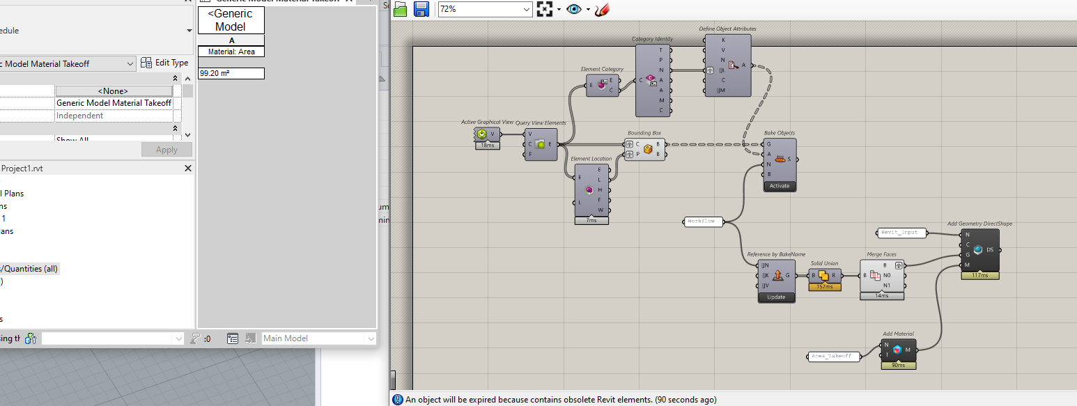
I’m thinking something like this… Elefront Required.
Bounding boxes are found for all elements and baked into Rhino. You would use Gumball Subobject select with Gumball plane set to Object to push/Pull any issue areas.
Group via UserText into the chunks you want, which would then be sorted in the Ref By BakeName component via Key/Value Attribute.
Then push into revit as direct shape with a material that would fill out a Material Area Schedule.
Apologies if this is a dumb question, but don’t the guys who created this in Revit need to get the beams to span correctly between the columns, and to line up accurately, so that the rebar can be designed correctly, so that the setting out points are accurate and so that the structure can be approved before construction? Then, having an accurate model, you should find it a lot easier to do the Rhino part.
Jeremy, The typical process is to have an Architectural Structural model, which provides preliminary sizing, costing and such. The model is then rebuilt in tekla or something similar to detail the connections and have true size beams, and subsequently coordinated with trade models in Navis or Revizto. The Arch Structural model can vary a lot to what finally gets fabricated and isn’t reliable information.
The breps that I share is one floor of just one building. Whole model involves 5 buildings with 7 floors. If I knew the parts that are causing the problem and fix them, there will be no problem. But the biggest hurdle for me now, since I don’t know what’s causing the problem, I have to review the whole model. And I don’t want to do that😥.