Starting surface needs at a minimum a PreserveEdges options like Patch has:
Preserve edges
Clamps the edges of the starting surface in place. This is useful if you are using a curve or points for deforming an existing surface, and you do not want the edges of the starting surface to move.
(Added) This option in Patch preserves the untrimmed edges of the starting surface.
The ability to set the level of preservation individually for each untrimmed edge including “not preserved/free” would be excellent.
My understanding is that this way of creating a patch cannot exactly follow the input surface (unless it is an untrimmed surface) like it can in patch. I’d be interested to see what happens if you get a Patch surface that is close to what you are after that is then further processed with FillSrf. Can you share an example file that shows what you are after?
I’ll modify my result to preserve untrimmed edges of the starting surface. That is what Patch does.
(Added) Essentially the outer control points of the starting surface are frozen before fitting the starting surface to the input curves, etc.
See below for what I’m am requesting. I’ll start with how I’ve been using Patch for fifeteen years, and then show how FillSrf currently works with a similar workflow
Patch result used as input to FillSrf result is very similar to FillSrf with the starting surface by itself. FillSrf Start 21.3dm (390.1 KB)
Start Surface with deviation from Input Curves
For this example I created a starting surface with untrimmed edges that matched most but not all of the perimeter of the input curves. I do this to avoid a singularity where the curved stem meets the keel. Instead I create a surface without a singularity and later trim it.
I frequently iterate: Create a relatively heavy start surface; use Patch to pull it to the input curves; check point deviation and add/remove knots as appropriate; use the revised surface as start surface for Patch.
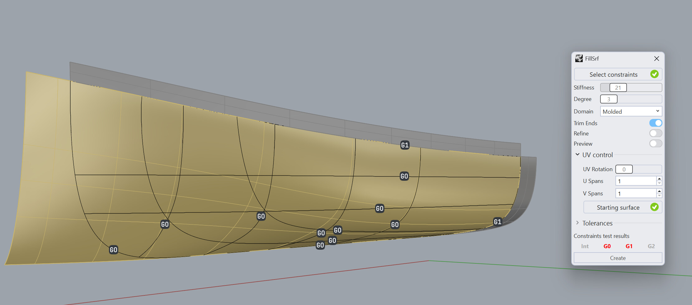
FillSrf
FillSrf with input curves, tangent constraint surfaces and starting surface
thanks for sending that file. Patch works different in that it can work better with conflicting constraints. @menno can hopefully explain why this is (or find ways to improve it)
If you give Fillsrf a little more freedom, you will get smoother results.
In the attached you can see what I mean. If you install the latest WIP, you’ll be able to double click the surface and see all the constraints and settings I used.
It’s by no means perfect, I did not do any analysis for deviation, but hopefully it gives you another angle of approach that can help get the surface you are after. FillSrf Start 21_sg.3dm (588.5 KB)
@Gijs Thanks for the reply. Perhaps the length of my post above has led to my original request being forgotten. It was not about a comparison of the smoothness of the results of FillSrf compared to Patch.
I requested that when a starting surface is used in FillSrf there be an option for the result to preserve the untrimmed edges of the starting surface, as is available in Patch. That allows the user to control the locations of untrimmed edges of the result through use of a starting surface.
In my example above the results of Patch using a starting surface with PreserveEdges option have untrimmed edges except for the curved stem. This is enable by the PreserveEdges option. In contrast the results of FillSrf are a larger surface with all edges trimmed. which are not desired.
An example of what I am after was requested, and my post above was in response to that request. But perhaps I provided too much information.
One of the thing I see is that the internal constraint curves are not consistent. The section, buttock and waterline curves should all intersect, but they do not. This is not the whole story though, and @gijs is on to something when using fewer constraint curves.
Thanks for creating the Youtrack item. I’ll review it when it is made public.
The internal curves are not completely consisistent, which is typical of vessel lines which have not been extensively reconciled. My need is a “best fit of” the starting surface to the inputs with the edges of the starting surface preserved.That is one of the reasons I use a starting surface to control the number of spans and knot distribution. It is also the reason I turned refine off in FillSrf.