I researched for a week (forum and test models (all of which are in a GH file below) included) why this fillet is not working and still cannot get it going.
Works for basic shapes… Found later and fixed manually an issue with my original curve’s form which i internalized - I redefined it but still will not work…
I want to filet the top face and bottom faces of the club head edges to avoid grass gripping and add super aerodynamic features (in wind tunnel testing right now LOL)… I just want to fillet the club head edges… I have further plans for asymetry in this fillet shape (like make one a round and the next a wing like shape (still to be tested - maybe more surface differences where i dont have to fillet… ) But i can’t do this fillet and it bothers me…
Im trying 3 different filleting techniques (the basic all edges (wrong default as i don’t want to filled vertical edges)), only horizontal edges, ball-rolling on the edge adaptation from a triangular edge and even another i found using edge proximity, none will work.
If i run a pipe around the edges it works perfectly however…
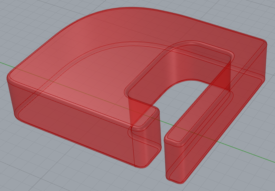
So in this picture, top of the GH script makes the yellow cube shape + filleting right, the bottom script and red shape will not work. I labeled the script t show where the cube and custom shapes go…
The yellow shape is perfect. The red shape is impossible to get to ‘fillet’ on the horizontal (xy plane) edges.
Last i tried was sorting/alligning the curve points - and i dont think it works… I see how some filleting might work. I had it working for only one segment (2 points of the curve) at some point but this was the bad curve… Can’t get it to work again…
I tried simplifying the curve/brep as much as possible (less control points - the font curve render module did a bad job or the font was not well done… So i redid the curve.
Well, you forgot to internalize the relevant curve(s)! And maybe get rid of all the irrelevant parts of the definition to make it a little easier for people who want to help.
The thinnest part of your brep is only about 1.6 units wide, which means that your fillet radius, if required for both opposing edges, can only be smaller than 1.6 * 0.5 = 0.8 units, or even less if there are other metrics to consider.
Another issue arises from you trying to fillet a seam edge that EdgesCvx fails to filter out. You need to chose the edges to fillet more carefully!
You can get a way cleaner base brep with less seam edges by more carefully constructing it!
I believe your value lists are also setup wrong! Counting starts at 0 (= Fillet) not 1!
In general, fillets are a tricky thing in Rhino and prone to breaking the geometry. It is thus a bad idea to try to parametrize their creation. You’d often have to manually correct mistakes.
Thanks. Im staying away from 3D plastic but not a bad idea for prototypes. Metal sintering printing remains an option in the future. I will CNC it in my garage out of wood (wenge or olive (very hard woods)), resin treated wood and/or aluminum. The optional insert might be a steel alloy and i might add a skeleton for rigidity if needed.
Still have to make the negative mold/holder piece for the CNC but that should be easier… Just have to think how i will mill the front face (cnc Z size allowance - 11cms - mold/waste board/etc)…
I got all the regulation sizing in the model and it is not easy to make a ‘inconspicuous’ club! Yes, that’s a thing i learned in my process - your putter might be banned in competition because too flashy…
The insert (hitting face) design and weights (screws) will have to be tried and tested… I got a pro waiting to try it who will help me out with the tuning… I have been testing how different putter clubs work/react - it’s quite a lot of weighting (for forgiveness), platting for sound/feedback. So about 5-10% done. But i wanted to have a ‘modular’ design first. Nothing like GH for this… Wasn’t as easy as I thought (unless you go with meh cube putter)…
I’m curious about this. I’m currently builing a DIY CNC with a z-axis clearance of 8.5cm. Do you first mill one side and then flip the part for milling the back? Is the negative mould to keep it in place?
I don’t know anything about golf, but the whole process is rather interesting.
yes, fliping the piece to make up for the lack of axii is the thing i think. I can carve x parts one way, x parts another way any degrees with the right ‘holder’ instead of only 2 ways (top and botton). Orient part for 37 degree shaft (for example) and you dont need a 5 axis machine.
Since i have a 3 axis only mill, the first challenge is to cut the hole for the club shaft to enter the club at 10 degrees which my cnc wont do. So i created a jig/holder to allow for this…
Now i have to figure out how to incline this jig at 10 degrees to do the T slots which will clamp the holder. But i think this is just a 10 degree surface plate which should be cnc’able on a 3 Axis machine. Same plate reversed and manually clamp the parts on the cnc. (first big metal job i will try…)
But how would you hold the part if you dont have T rails in your cross section profiles? The width of the club will be variable so that’s why im thinking of t rails…
Im thinking right now of making a similar plate as the grey (note the walls hold the block). For milling the holder at 10 degrees for the t rails only im thinking of making a similar part - cnc the face to get an average 10 degrees surface with scallops granted but scallops will be helpfull to hold the ‘holder’ part when i mill the rails and a flat surface above at the right angle. Just will have to be manual improvised clamping…
Would that work? The heavy line is the one i would flatten and then get that 10 degree set at the right angle…
I hacked this for a quick graphic - rotated xy somewhere the top plate (please forgive me)
I often use threaded inserts to put threaded holes where I need clamps… either straight into my router bed (sacrificial MDF sheet) or into the jigs them selves.
You could just manually drill and tap holes where you need clamps?
The idea of contour frames is not bad but how to hold the club face or the main holder laterally with rails where you can’t clamp at the right size and add pressure (which would be only one profile (screws needed per profile on top - lots of changes if we assume the club’s length changes which it will.
With rails, you can lock them, with profiles holding the part, you would need a lateral screw maybe… mmm seems more complicated and less solid… I’ve been thinking of adding perpendicular rails too (to prevent the part sliding down…
the lack of rigidity in one axis might be troublesome if i mill hardwoods or steel… Love this challenge! Always a new detail to think of…
Wouldn’t it be easier to simply mill the shape of the club and do the hole with a jig and a hand drill (or drill press)? I’ve used 3d printed drill guides before and they work great.
Since your jig seems to be mainly for drilling that hole, it seems like a giant waste of material and time to me.
yes, youre right. It’s just that i never made a perfect hole by hand (i have 4-5 drills)… even with guides. If this is steel, i think it would be easier to tap drill or bit by bit with regular milling a hole + chamfer above.